

InvAmp 1.0.0.0 — User manual
Use your browser's Print command and choose “Save as PDF” to keep a copy.
- What's new
- Installation and requirements
- About InvAmp
- Opening the panel and finding your way
- Home
- Selection
- Work Mode — display profiles
- Work Mode — screen capture
- Assembly Tools — placement and mirror
- Assembly Tools — isolate
- Assembly Tools — checking an assembly
- Rename — rename or duplicate a part with its drawing
- Rename — naming groups
- Blocks — sketch block library
- Workspace — reuse components from your folders
- Eng. Tools — calculators and tables
- Utilities — tools for the active document
- Utilities — manufacturing pack
- BOM — bill of materials
- BOM — columns
- Linked Params — parameters from a reference part
- Design Report
- Settings
- Troubleshooting — messages and the log
- Troubleshooting — the panel
What's new
This is the first release of InvAmp, version 1.0.0.0.
InvAmp adds one panel to Autodesk Inventor. The panel holds twelve pages. Each page groups the tools for one kind of work.
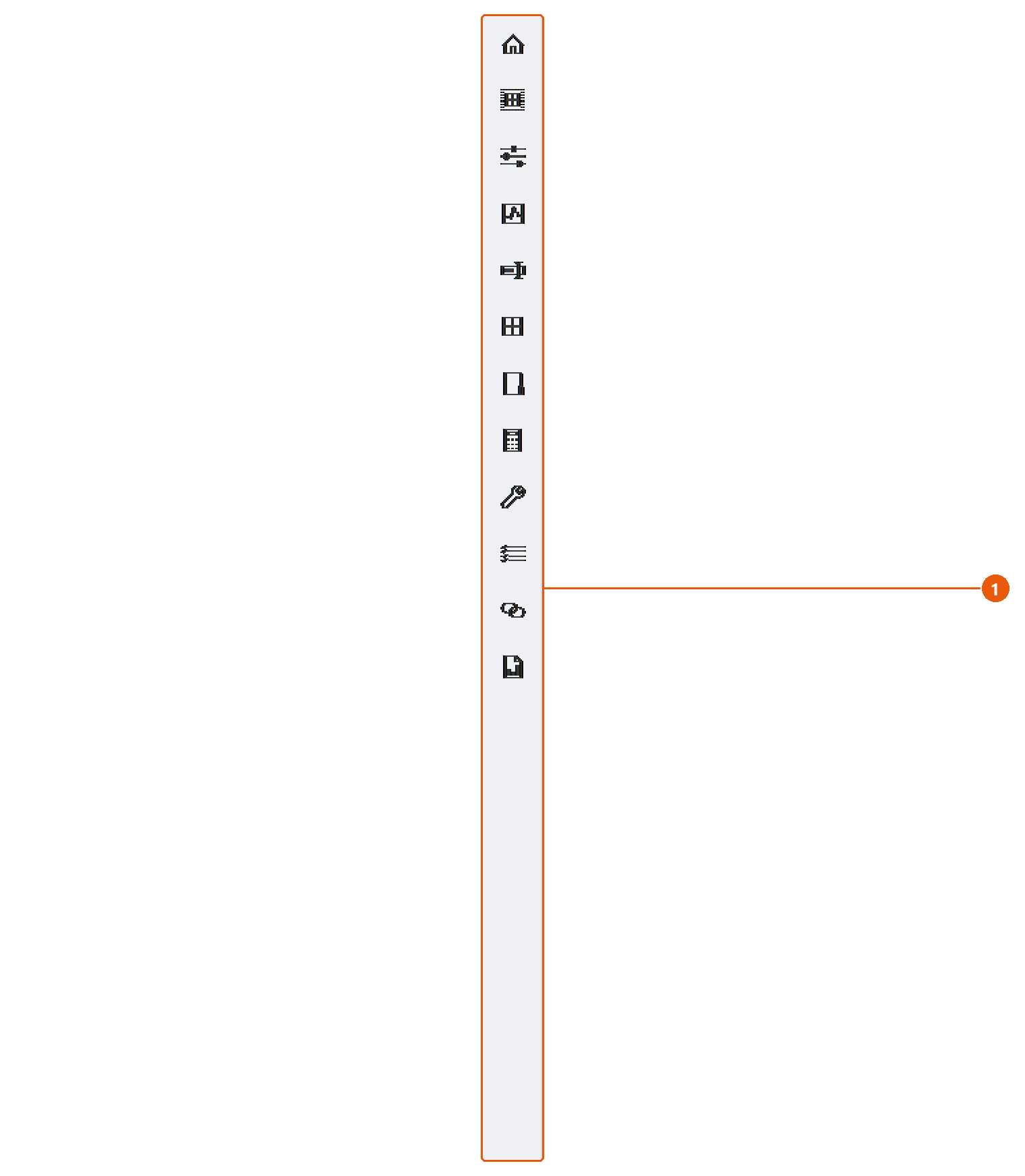
The icon bar 1 lists the pages in this order:
| Page | What it is for |
|---|---|
| Home | Overview, settings and environment information. |
| Selection | Properties and a preview of the current selection. |
| Work Mode | Display profiles and screen capture. |
| Assembly Tools | Placement and part tools for the selected component, and assembly checks. |
| Rename | Rename a part and its drawing to a standard name. |
| Blocks | Insert sketch blocks from reference parts. |
| Workspace | Reuse components from your own folders. |
| Eng. Tools | Cylinder forces and standard part tables. |
| Utilities | Batch export, drawings, parameters and more. |
| BOM | List the assembly's bill of materials and export it. |
| Linked Params | Pull parameters from a reference part. |
| Design Report | Check an assembly and export a report. |
Tip:Hover over an icon to see the same description in a tooltip.
Note: You can hide pages you do not use. See Settings.
Installation and requirements
Requirements
- Autodesk Inventor 2024, 2025 or 2026, on 64-bit Windows.
- Nothing else. InvAmp installs two files,
InvAmp.dllandInvAmp.addin, and writes nothing to the Windows registry.
Install with InvAmp-Setup
InvAmp is installed with InvAmp-Setup.exe. Ask for it with the request form on invamp.net.
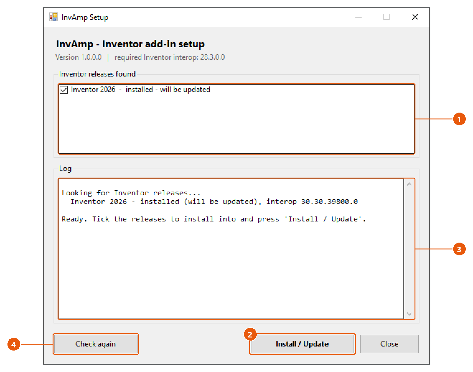
- Close Inventor. The setup cannot replace the add-in while Inventor has it loaded.
- Run
InvAmp-Setup.exe. It lists every Inventor release it finds on the computer 1, and whether InvAmp is already installed there. - Tick the releases to install into, then press Install / Update 2.
- Read the log 3. It names the folder each file was written to, and checks each file after writing it.
- Start Inventor.
The setup copies the files into %APPDATA%\Autodesk\Inventor <version>\Addins. Run it again to update an existing installation.
Note:The setup refuses to install while Inventor is running, and says so. Close Inventor completely and press Check again 4.
Note: A release older than the one InvAmp was built for is marked INCOMPATIBLE: Inventor could not load the add-in there.
Check that InvAmp is loaded
- In Inventor, open Tools → Add-Ins.
- Find InvAmp in the list. Make sure it is loaded and Load Automatically is ticked.
Remove InvAmp
Close Inventor and delete InvAmp.dll and InvAmp.addin from the Addins folder above. The setup has no uninstall option of its own.
About InvAmp
InvAmp is an add-in for Autodesk Inventor by TT Engineering. It collects the everyday jobs around parts, assemblies, sheet metal and drawings into one dockable panel.
Use it to:
- Read and edit the iProperties of whatever is selected, with a preview.
- Place, isolate and mirror components, and check an assembly before it goes to the shop.
- Rename a part together with its drawing.
- Reuse components and sketch blocks from your own libraries.
- Export a whole assembly in one run: STEP, PDF, DXF and DWG, nesting drawings and a manufacturing pack.
- Build a bill of materials and send it to Excel.
- Run a design report on an assembly and save it as a PDF.
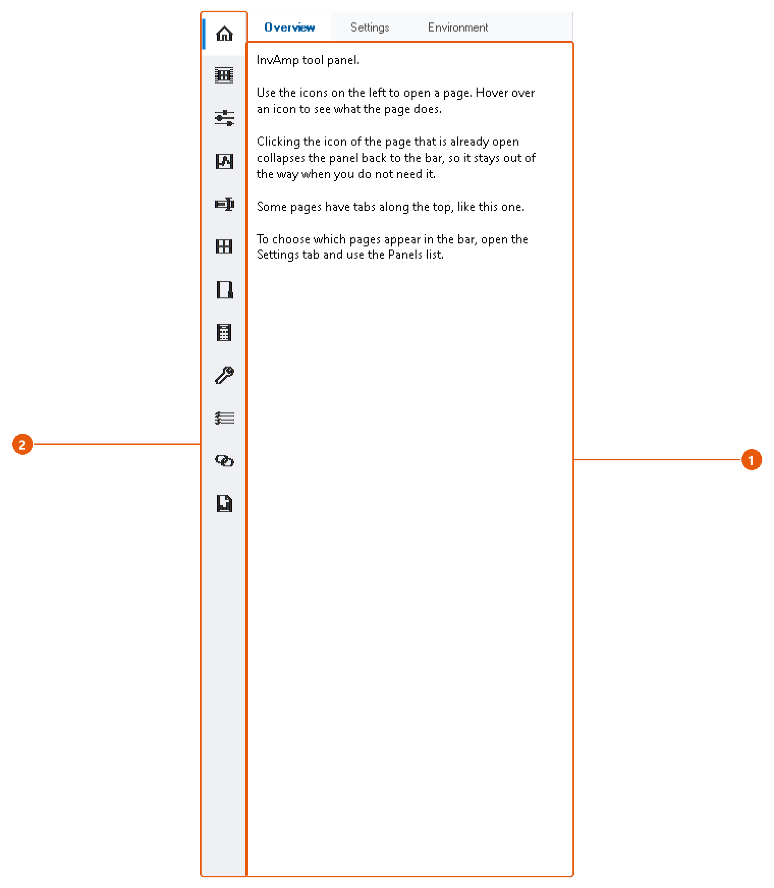
Pages open in the panel's page area 1. Choose a page from the icon bar 2.
Where InvAmp keeps its data
InvAmp writes its settings to %APPDATA%\InvAmp\settings.ini. It writes a log of failures to %APPDATA%\InvAmp\log. Files it produces, such as exports and drawings, go to folders you choose.
Note:InvAmp sends nothing over the network. The one exception is the optional Google Sheets export of a bill of materials, which works only after you enter your own Google credentials. See Settings.
Opening the panel and finding your way
Show or hide the panel

- Open the Tools tab of the ribbon.
- Press InvAmp 1 in the InvAmp panel, at the right-hand end of the tab. The button shows the panel, and hides it again on the next press.
The button is on the Tools tab of the part, assembly, drawing and presentation ribbons, and on the ribbon Inventor shows when no document is open.
The panel docks on the right the first time. Drag its title to dock it on another edge, or leave it floating. Inventor remembers where you put it.
The panel collapsed
When no page is open, the panel shrinks to the icon bar 1. It takes very little room, and it has no close button.
A page open
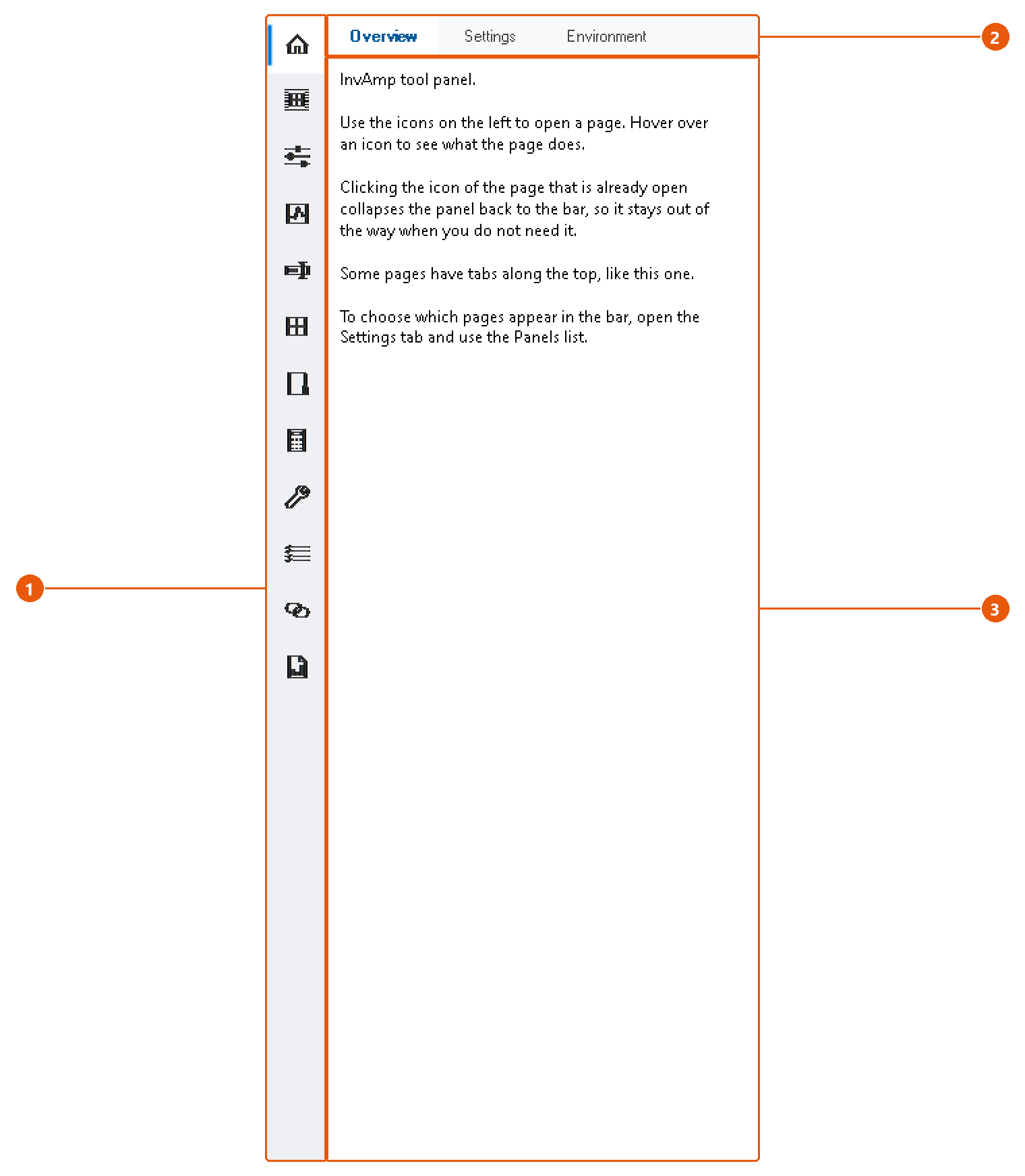
- Click an icon in the icon bar 1. The panel widens and shows that page.
- If the page has sub-pages, pick one from the tabs along the top 2.
- Work in the page itself 3.
- Click the icon of the open page again to collapse the panel back to the bar.
Tip:Hover over an icon to see what its page does.
The panel remembers the width you drag it to and uses it the next time a page opens. Each page also keeps its own state while Inventor runs: switch to another page and back, and your entries are still there.
Most pages report the result of an action in a status line at their bottom edge.
Home
Home is always in the icon bar; it cannot be hidden. It has three tabs: Overview, Settings and Environment.
- Overview is a short reminder of how the panel works: icons open pages, the open page's icon collapses the panel, and tabs switch sub-pages.
- Settings holds every InvAmp preference. See Settings.
- Environment shows facts about this installation. Use it when you contact support.
Read the environment
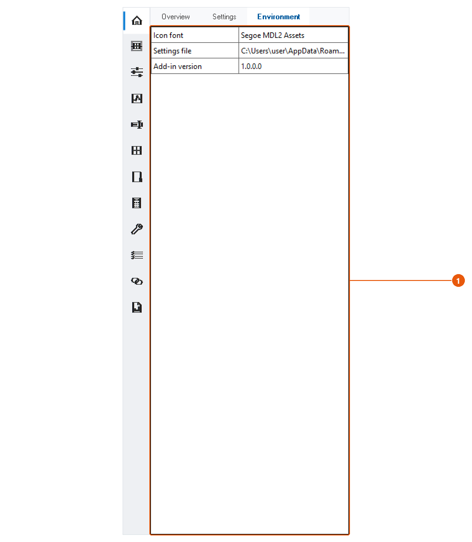
- Click Home in the icon bar, then the Environment tab.
- Read the table 1. It has three rows:
| Item | What it tells you |
|---|---|
| Icon font | The Windows font the panel's icons are drawn from. If it is missing, InvAmp draws simple geometric icons instead. |
| Settings file | The full path of the settings.ini InvAmp is using. |
| Add-in version | The version of InvAmp that is loaded. |
Tip:Quote the add-in version when you report a problem. It tells us exactly which build you have, and the settings file path tells us where to look when a setting is not remembered.
Selection
The Selection page shows the iProperties of whatever you select in Inventor, with a preview. You can edit the properties in place.
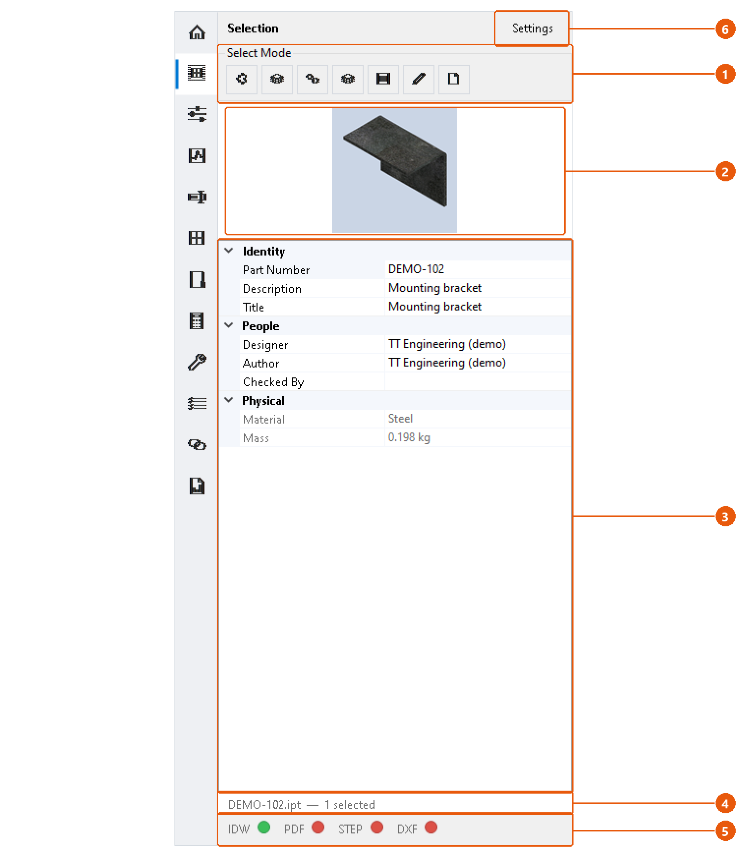
Inspect a component
- Open a part, assembly or drawing.
- Click Selection in the icon bar.
- Select a component in the graphics window or the browser. With nothing selected, the page shows the active document itself.
- Check the preview 2 and the property grid 3.
- Read the status line 4. It names the file and how many objects are selected.
The property grid 3 groups the properties into sections such as Identity, People and Physical. Greyed-out rows are read-only. Mass is shown in kilograms. A row reads (not available) when the document does not carry that property.
Edit a property
- Click the value in the property grid 3.
- Type the new value and press Enter.
The value is written into the document straight away. The document is not saved: save it in Inventor to keep the change.
Change what Inventor selects
The Select Mode buttons 1 switch Inventor's selection priority, for example Component Priority, Part Priority or Select Faces and Edges. Hover over a button to see its name. The buttons on offer depend on the active document.
If Inventor refuses a mode, for example while a command is running, the status line says so.
See which files exist beside the part
The file lamps 5 show whether a drawing (IDW or DWG), PDF, STEP or DXF file with the same name sits in the part's folder. Green means the file exists; red means it does not; grey means nothing is selected.
Note:The lamps are off by default. Turn them on in the settings 6.
Settings
Press Settings 6 to open the Selection panel settings.
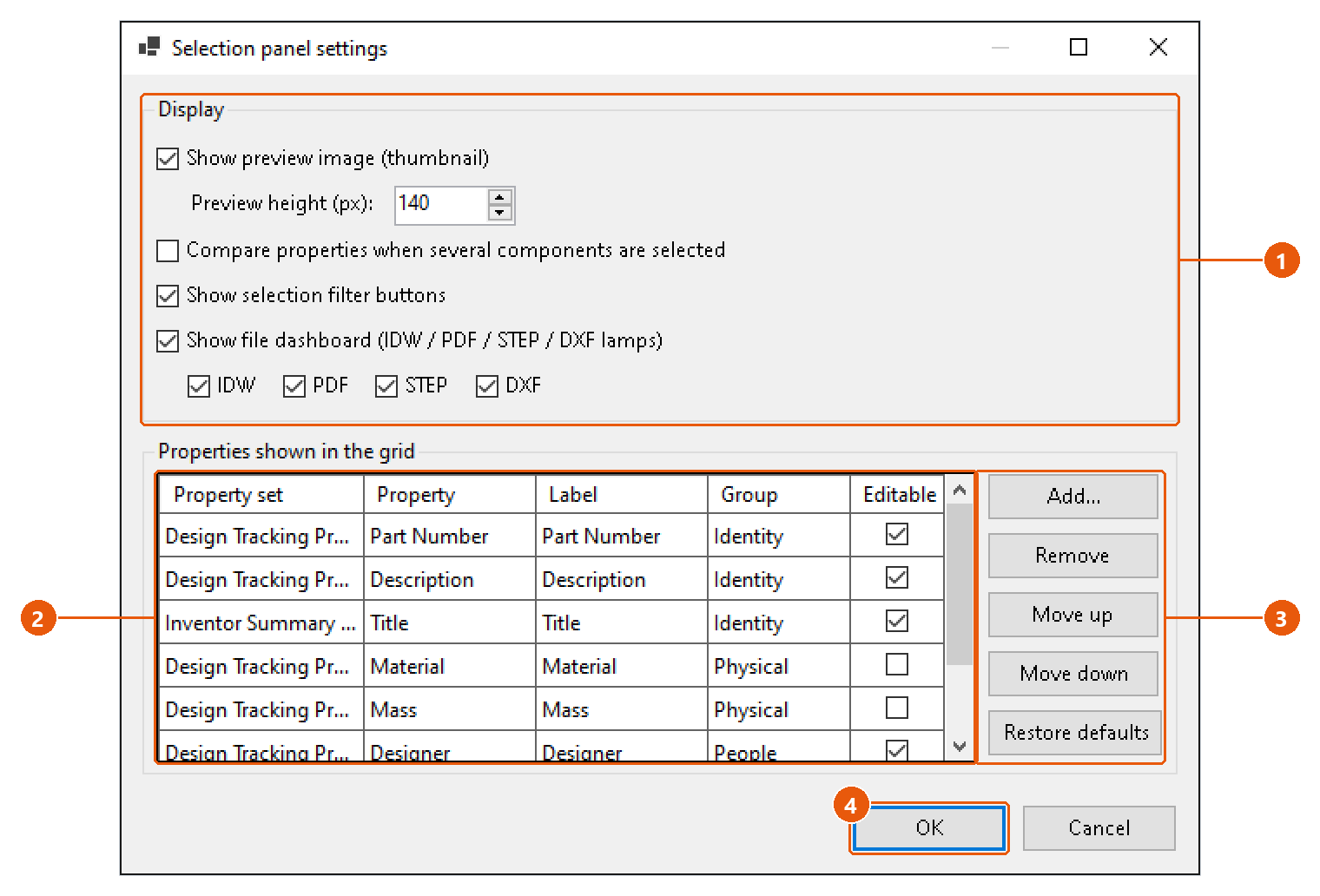
- Choose what the page shows 1: the preview and its height, the multi-selection comparison, the Select Mode buttons and the file lamps.
- Choose which properties appear in the grid 2. Tick Editable to allow editing a property.
- Add, remove or reorder properties with the buttons beside the grid 3. Restore defaults brings back the built-in list.
- Press OK 4.
Tip:Turn on Compare properties when several components are selected to see only the values that all selected components share.
Work Mode — display profiles
A work profile is a named set of Inventor display settings: colour scheme, background, UI theme, projection, display quality, display mode and textures. Apply a profile to change all of them in one click.
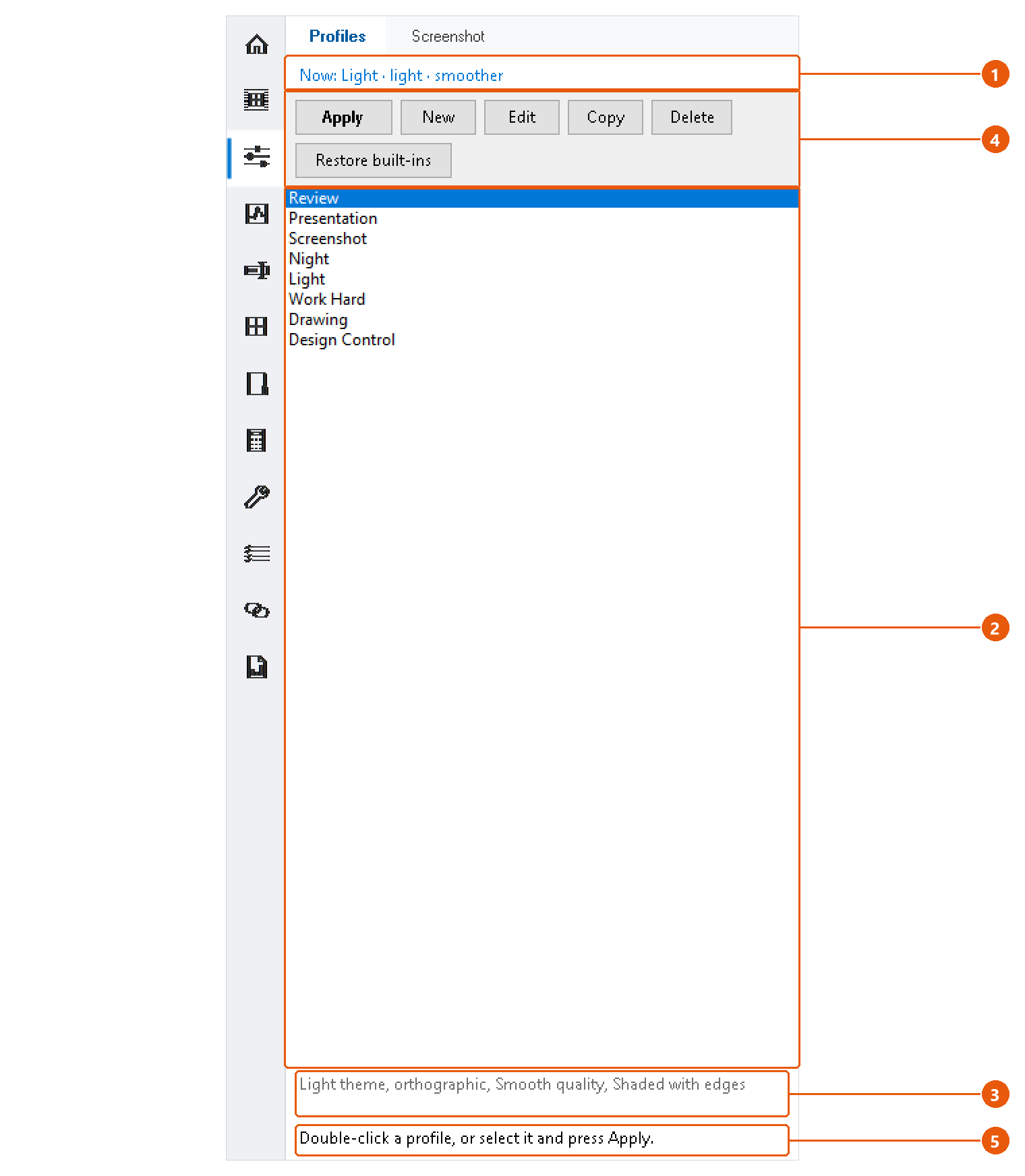
Apply a profile
- Click Work Mode in the icon bar, then the Profiles tab.
- Read the line at the top 1. It shows what Inventor displays right now.
- Select a profile in the list 2. The text below the list 3 says what the profile changes.
- Press Apply in the button row 4, or double-click the profile.
- Read the status line 5. Green means every setting was applied. Orange means some could not be applied, and it says which.
Note:A profile changes only the settings it names. A setting left as (leave unchanged) keeps Inventor's current value. So a profile can switch only the theme and leave everything else alone.
Some settings do not apply everywhere. For example, a drawing has no display mode. The status line reports those instead of failing silently.
The built-in profiles
InvAmp comes with eight profiles: Review, Presentation, Screenshot, Night, Light, Work Hard, Drawing and Design Control. You can edit them, but you cannot delete them, so the list is never empty. Restore built-ins resets them to their defaults. Profiles you created are kept.
Create or change a profile
- New opens the profile editor with an empty profile.
- Edit opens the selected profile.
- Copy adds a copy named
<name> (copy). A copy is always your own profile, even when the original is built in. - Delete removes a profile you created, after asking.
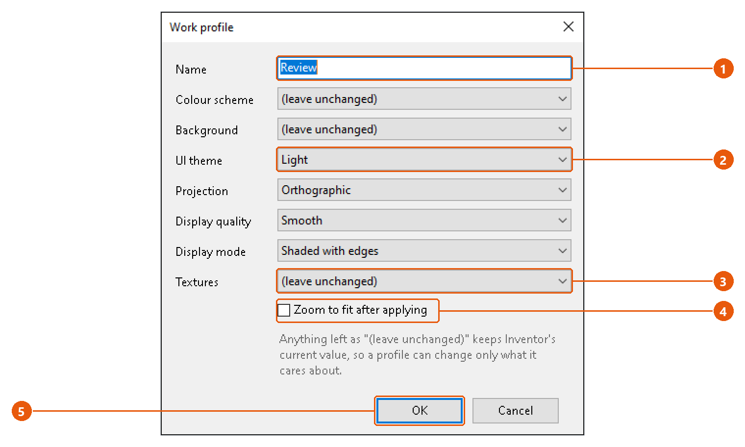
- Type a name 1.
- Pick a value for each setting you want the profile to change, for example the UI theme 2.
- Leave the others as (leave unchanged) 3.
- Tick Zoom to fit after applying 4 if the view should fit the model afterwards.
- Press OK 5.
Work Mode — screen capture
Save the current Inventor view as an image at any resolution, independent of your screen size. Or save four isometric views in one go.
Capture the current view
- Open the part or assembly and set up the view.
- Click Work Mode in the icon bar, then the Screenshot tab.
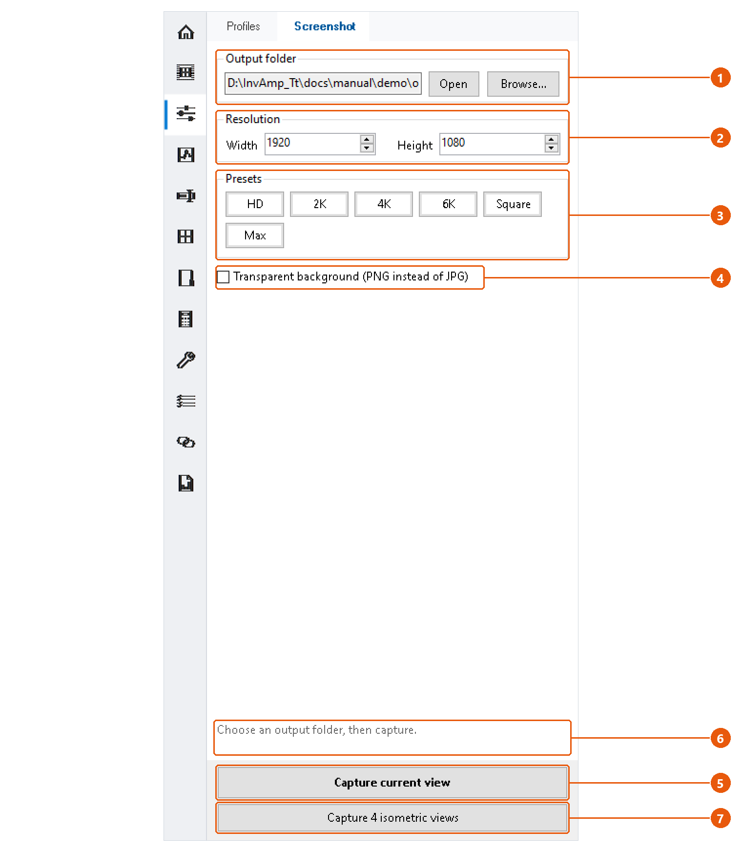
- Press Browse... and choose the output folder 1. Open shows the folder in Windows Explorer.
- Enter the width and height in pixels 2, or press a preset 3.
- Tick Transparent background 4 to save a PNG with no background. Otherwise the image is a JPG.
- Press Capture current view 5.
The status line 6 names the saved file. Click it to open the image.
The file is named after the document, followed by the date and time, for example DEMO-100_SS_261016_143005.jpg. Repeated captures never overwrite each other.
| Preset | Size in pixels |
|---|---|
| HD | 1920 × 1080 |
| 2K | 2560 × 1440 |
| 4K | 3840 × 2160 |
| 6K | 6000 × 3375 |
| Square | 2000 × 2000 |
| Max | 6000 × 6000 |
Capture four isometric views
- Choose the output folder, resolution and background as above.
- Press Capture 4 isometric views 7.
InvAmp looks at the model from above, from all four corners in turn: front right, front left, back left and back right. It fits the model each time and saves one image per corner, named ..._IsoTopFrontRight, ..._IsoTopBackLeft and so on. Your own view is restored afterwards, and the status line says how many images were saved.
Note:Without an output folder, capture stops and the status line asks you to choose one first.
Assembly Tools — placement and mirror
The Placement section constrains components in fewer clicks than Inventor's own Constrain command. Mirror part makes a mirrored twin of a part. Open an assembly, then click Assembly Tools in the icon bar.
Drop a component onto the assembly origin
- Select one component in the browser or the graphics window.
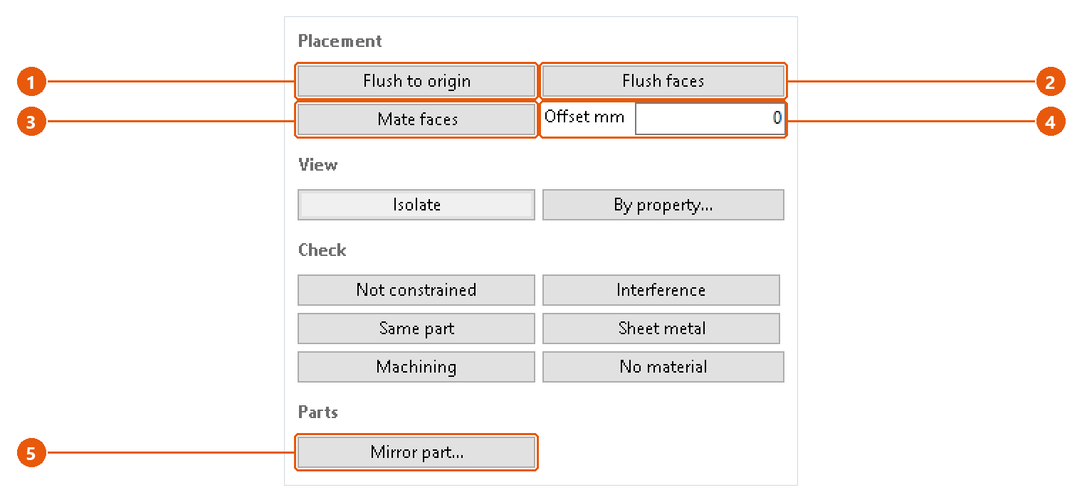
- Press Flush to origin 1.
InvAmp flushes the component's XY, XZ and YZ origin planes against the assembly's, which lands it on the assembly origin. If a plane would over-constrain the component, InvAmp skips it and names it on the status line.
Note:A grounded component cannot be constrained. Unground it first.
Line up several parts with one face
- Click the face everything should line up with. Pick this one first: it is the reference.
- Ctrl-click one face on each part that has to line up with it.
- Set the gap in Offset mm 4. 0 puts the faces together; a negative number goes the other way. An empty box counts as 0.
- Press Flush faces 2 or Mate faces 3.
| Button | Result |
|---|---|
| Flush faces | The faces become coplanar and point the same way, like two backs in one plane. |
| Mate faces | The faces touch and point at each other, like a plate landing on a base. |
The status line says how many faces were constrained. If Inventor refuses one constraint, the run continues and the message names the part that did not move.
Note:The offset accepts both 1.5 and 1,5. Anything else stops the run.
Make a mirrored part
- Select a part in the assembly. Mirror works on parts, not on subassemblies.
- Press Mirror part... 5.
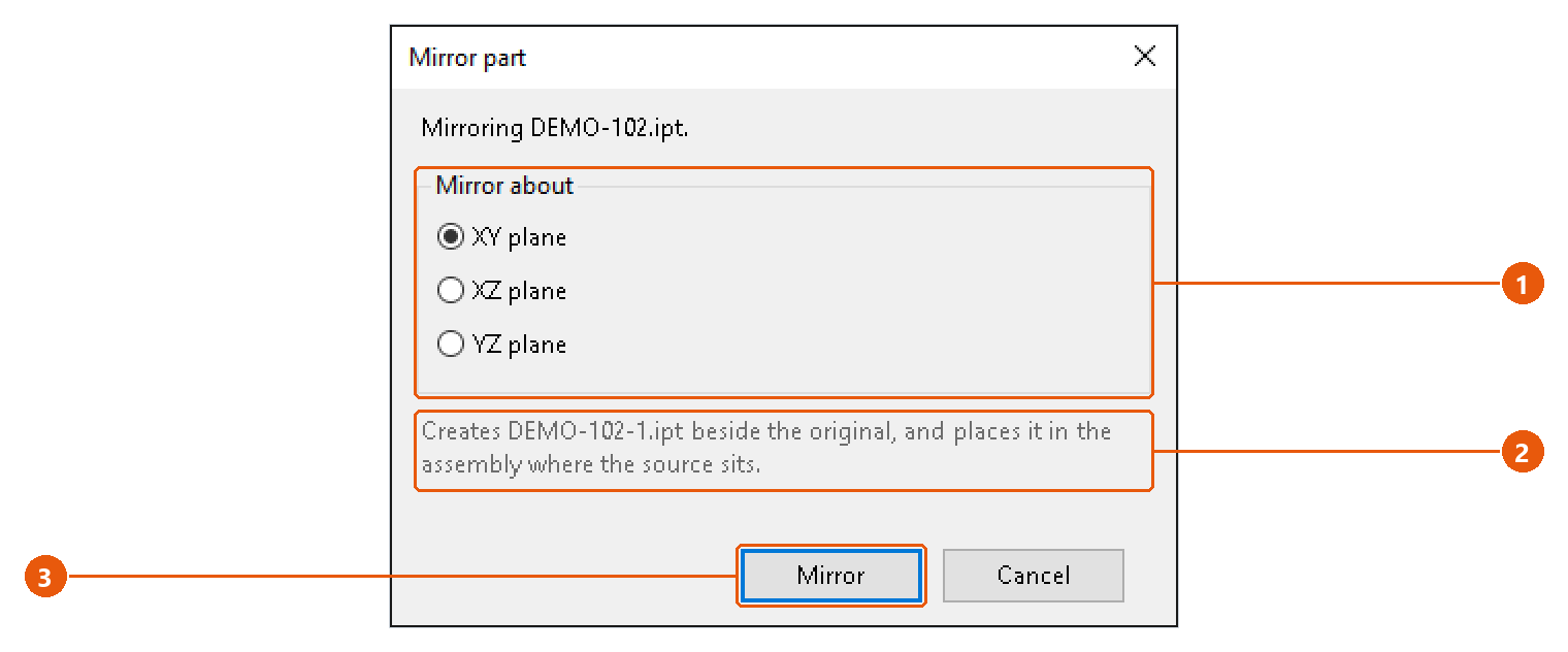
- Choose the mirror plane 1: XY, XZ or YZ.
- Read the line below 2. It names the file that will be created.
- Press Mirror 3.
InvAmp copies the source file, so the twin keeps its iProperties and template. It empties the copy of its features, sketches and parameters, then derives the original back in, mirrored about the chosen plane. The twin is placed in the assembly where the source sits and is left selected. No constraints are added.
The twin's name is the source name plus a suffix, -1 by default. Change the suffix in Home → Settings → Assembly tools.
Note:InvAmp never overwrites a file. If the twin's file already exists, the dialog says so and Mirror stays disabled.
Assembly Tools — isolate
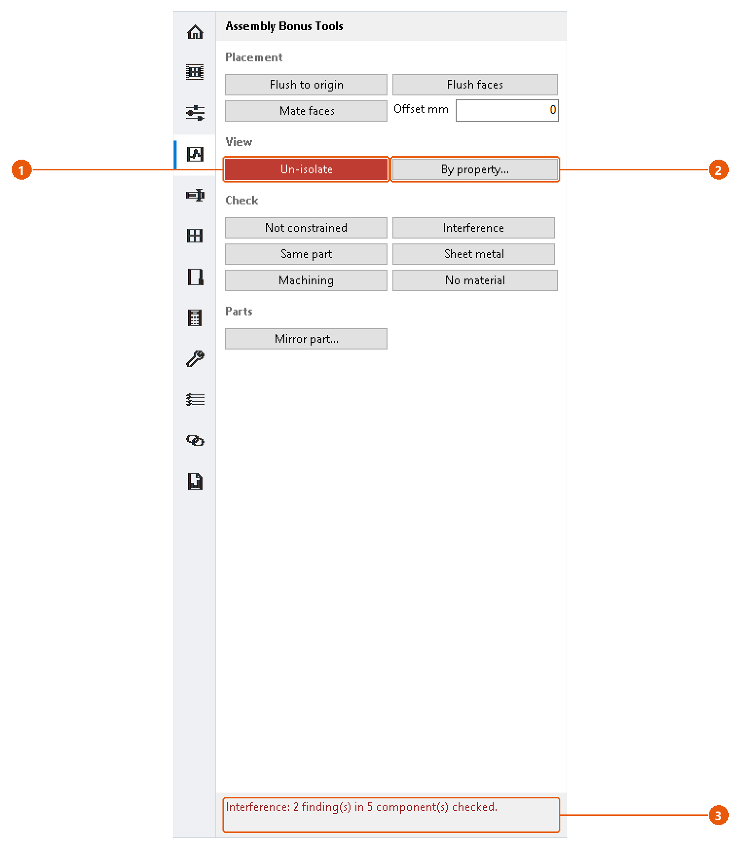
Isolate hides everything except the components you care about, and puts the assembly back exactly as it was afterwards.
Isolate the selection
- Select one or more components. A part nested inside a subassembly is fine: the subassembly stays visible and its other parts are hidden.
- Press Isolate 1. Everything else is hidden.
- The button turns red and reads Un-isolate 1 while anything is hidden.
- Press Un-isolate to bring every component back.
"Exactly as it was" means exactly: a component that was already hidden before you isolated stays hidden afterwards.
InvAmp remembers the isolate on disk. If Inventor closes while the assembly is isolated, the red Un-isolate button is there the next time you open the page; its tooltip names the assembly. Open that assembly and press the button to put the components back. If the assembly file no longer exists, the memory is dropped.
Note:If the selection is already everything that is visible, nothing is hidden and the status line 3 says so.
Isolate by a property
Find components by an iProperty, for example every part whose part number contains BRK.
- Press By property... 2.
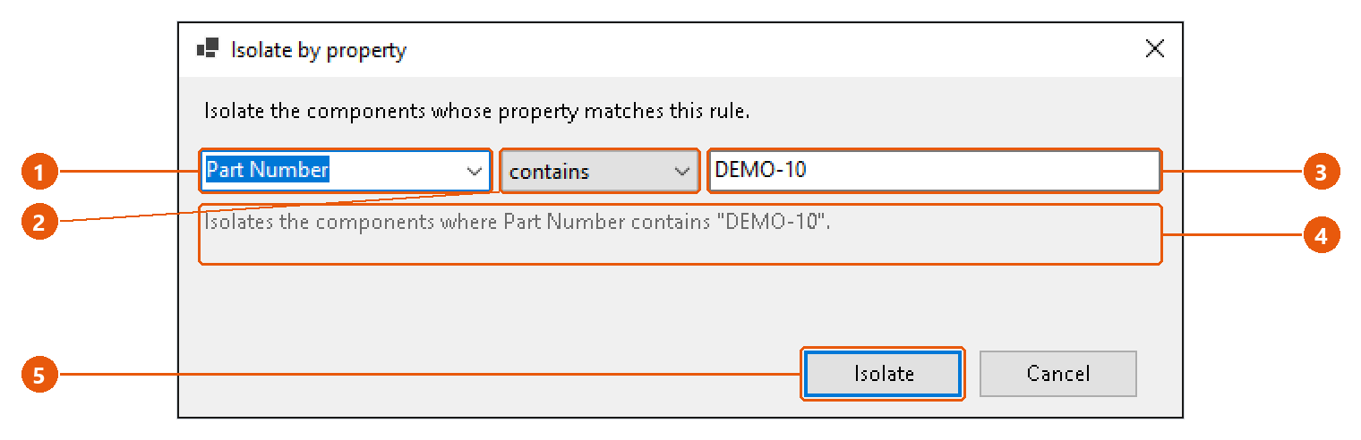
- Choose or type a property 1. The list offers the properties the open document carries; you can type any other name.
- Choose a condition 2: equals, contains, is not or is empty.
- Type the value 3. is empty needs no value.
- Read the rule back as a sentence 4.
- Press Isolate 5.
InvAmp lists the matching components and isolates them. The rule is remembered for next time, even when it matched nothing.
Tip:is empty also finds parts that do not carry the property at all. Use it to find the parts nobody filled in.
Assembly Tools — checking an assembly
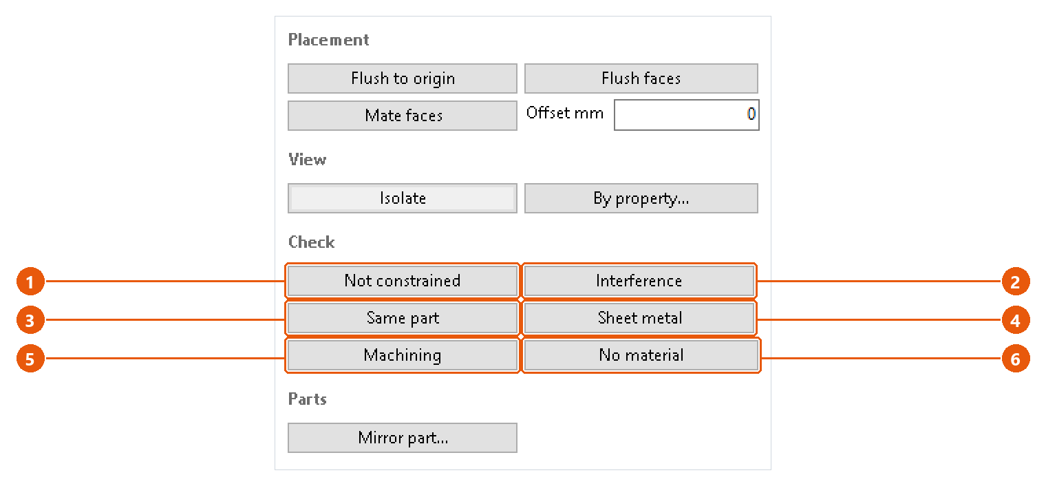
The Check section runs six checks over the open assembly. Each one lists what it found and isolates those components, so the next thing on screen is the parts that need attention.
Run a check
- Open the assembly and click Assembly Tools in the icon bar.
- Press a check button. A progress window shows while InvAmp walks the components. Cancelling it changes nothing: the checks only read.
- If nothing is found, the status line says so in green.
- Otherwise the findings open in a report, and the components concerned are isolated.
| Check | What it finds |
|---|---|
| Not constrained 1 | Components that can still move. Grounded components are not reported: being fixed in place is their constraint. |
| Interference 2 | Every overlapping pair in the assembly, with the volume of the overlap. |
| Same part 3 | Parts that look identical but are saved under different file names. The match uses volume, size and face and edge count: treat it as candidates, not proof. |
| Sheet metal 4 | Sheet metal parts with no flat pattern, and parts whose style thickness disagrees with the geometry. |
| Machining 5 | Parts that will be cut from solid, and how much of the billet each one throws away. |
| No material 6 | Parts with no material, with the template's placeholder material, or with a material that has no density. |
Read the report
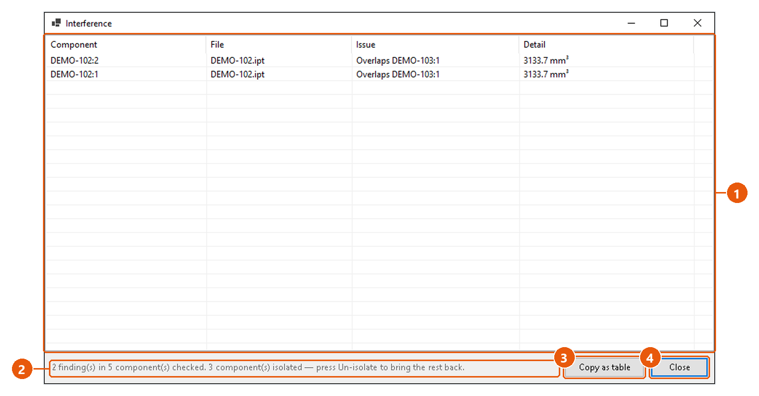
- Read the findings 1: the component, its file, the issue and a detail such as the overlap volume.
- Read the summary 2. It says how many components were checked and how many were isolated.
- Press Copy as table 3 to copy the findings. Paste them straight into a spreadsheet.
- Press Close 4.
When you are done with the findings, press the red Un-isolate button to show the rest of the assembly again.
What the checks skip
- Machining treats a part as machined when it is not sheet metal, not from Content Center and not purchased. Above the waste threshold, a part is flagged as worth a second look. The threshold is Machining waste % in Settings, 70 % by default. It is a prompt, not a verdict.
- No material skips Content Center and purchased parts. The placeholder names it looks for are Placeholder materials in Settings,
Generic, Defaultby default.
Tip:Run Sheet metal before you produce nesting drawings. A part with no flat pattern is skipped by nesting without a word.
Rename — rename or duplicate a part with its drawing
Rename gives a part or an assembly a new name and takes its drawing along, so the drawing still shows the renamed model. Duplicate writes a copy instead.
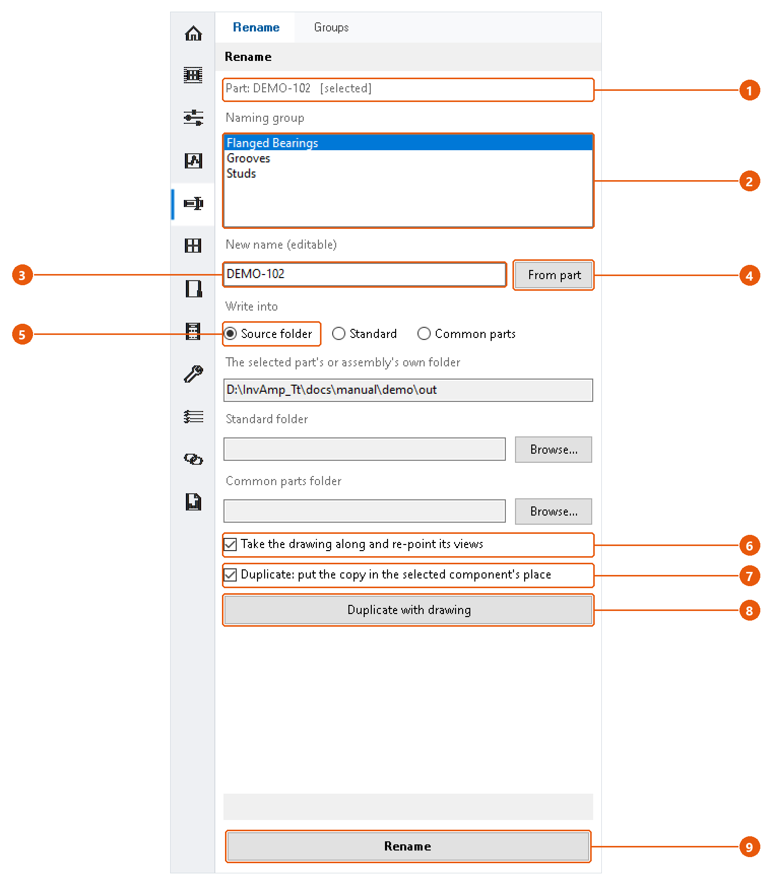
Choose what to rename
- Open the assembly and select the component in the browser or the graphics window. With nothing selected, InvAmp uses the active document.
- Click Rename in the icon bar, then the Rename tab.
- Check the source line 1. It names the part or assembly InvAmp will work on, and whether it came from the selection.
Choose the new name
The name box 3 fills itself, and you can edit it:
- Pick a naming group 2 to get the group's next name, for example
FLB_001. - Select another part in Inventor to get that part's current name, ready to change a character or two.
- Press From part 4 to put the part's own name back.
Once you type in the box, selecting parts in Inventor no longer overwrites it.
Choose where the files go
Pick a destination 5:
| Option | Folder |
|---|---|
| Source folder | The part's or assembly's own folder. |
| Standard | A folder you set with Browse.... |
| Common parts | A folder for parts shared across machines, set with Browse.... |
Rename
- Tick Take the drawing along and re-point its views 6 to rename the drawing too.
- Press Rename 9.
- Confirm the summary.
InvAmp saves the model under the new name. With the drawing option on, it also saves the drawing under the new name and points its views at the renamed model. The original files stay on disk, so a mistake can always be undone by hand.
Note:The open assembly switches to the renamed file at once, but Inventor does not mark the assembly as changed and may not ask you to save it. Save the assembly yourself; otherwise it opens the old file, which is still on disk, the next time.
Duplicate
- Leave the name box untouched to get the next free name in the family, or type a name.
- Tick Duplicate: put the copy in the selected component's place 7 to swap the component for the copy.
- Press Duplicate with drawing 8 and confirm.
The original and its drawing are not touched. If the copy was swapped in, save the assembly to keep it.
Note:Duplicating an assembly copies only the assembly file. The copy uses the same parts as the original, so changing one of them changes both assemblies.
Note: A taken name, or a character Windows does not allow in file names, stops the run.
Rename — naming groups
A naming group hands out numbered names in a fixed format, for example FLB_001, FLB_002. Pick a group on the Rename tab and the next name appears in the name box.
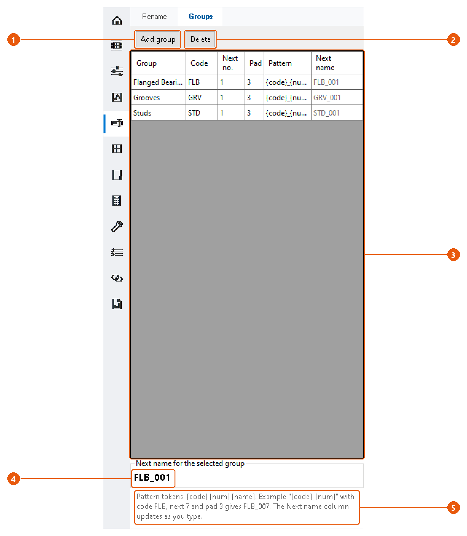
Set up a group
- Click Rename in the icon bar, then the Groups tab.
- Press Add group 1, or edit a row of the table 3 directly.
- Fill in the columns:
| Column | Meaning |
|---|---|
| Group | The name shown in the list on the Rename tab. |
| Code | A short code used in the name, for example FLB. |
| Next no. | The number the group hands out next. |
| Pad | How many digits the number gets. 3 turns 7 into 007. |
| Pattern | The name template. |
| Next name | The name the group will produce next. Read-only; it updates as you type. |
- Check the next name for the selected group 4.
The pattern can use three tokens 5: {code}, {num} and {name}. Anything else is copied as it is. The default pattern {code}_{num} with code FLB, next number 7 and pad 3 gives FLB_007.
To remove a group, select it and press Delete 2, then confirm.
When does the number move on?
The group's number goes up by one only when the name you rename or duplicate to is exactly the name the group offered. If you edit the name before applying it, the number stays where it is, so no number is skipped.
InvAmp comes with three example groups: Flanged Bearings (FLB), Grooves (GRV) and Studs (STD).
Blocks — sketch block library
Blocks keeps a library of sketch blocks in ordinary part files. Check a block out into the part you are working on, or send the blocks of the active part to a library file for later jobs.
Register library files
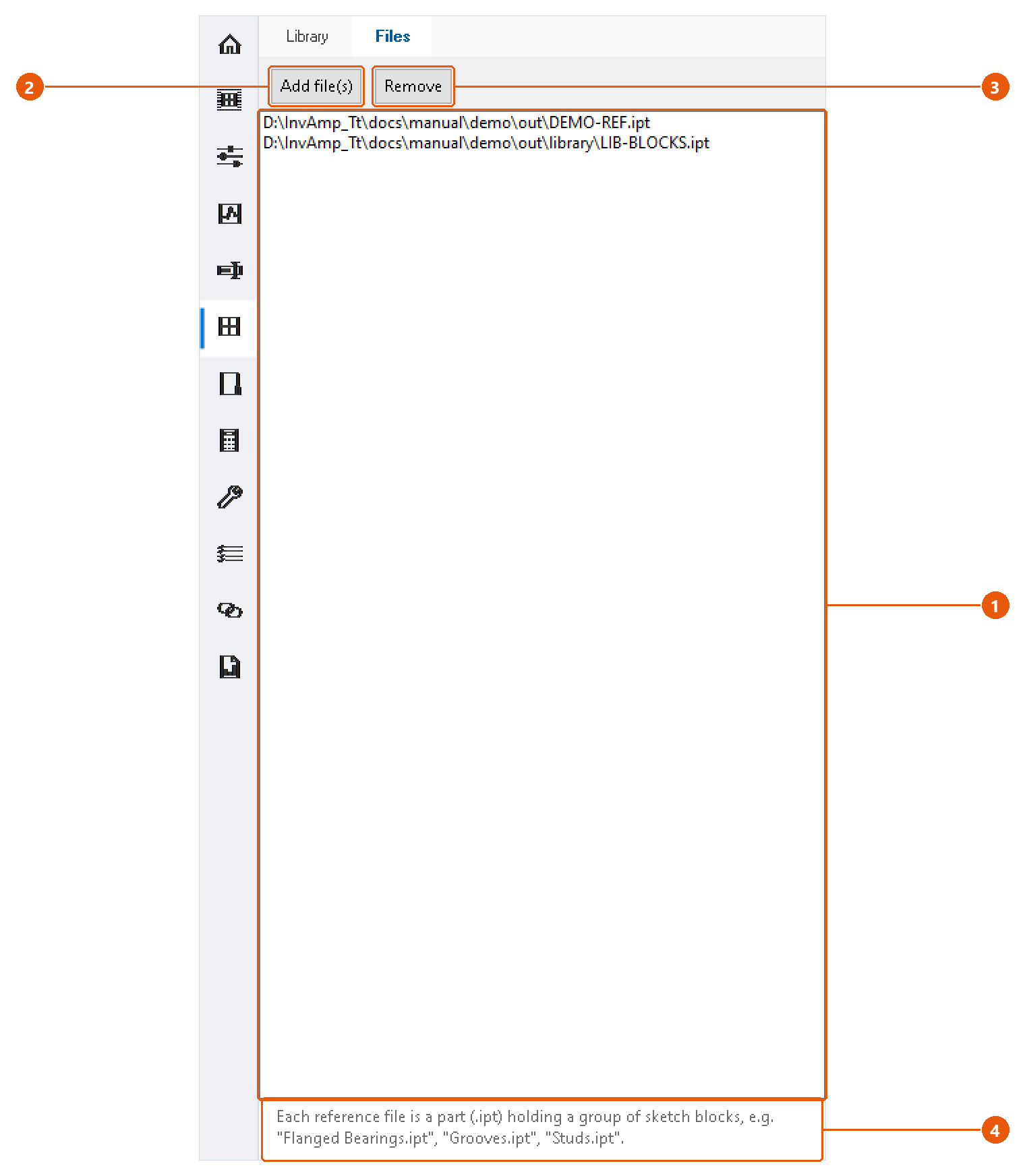
- Click Blocks in the icon bar, then the Files tab.
- Press Add file(s) 2 and choose one or more part files that hold sketch blocks.
- The files appear in the list 1. To drop one, select it and press Remove 3.
Each library file is an ordinary .ipt. Its sketch block definitions are the library 4.
Check out a block
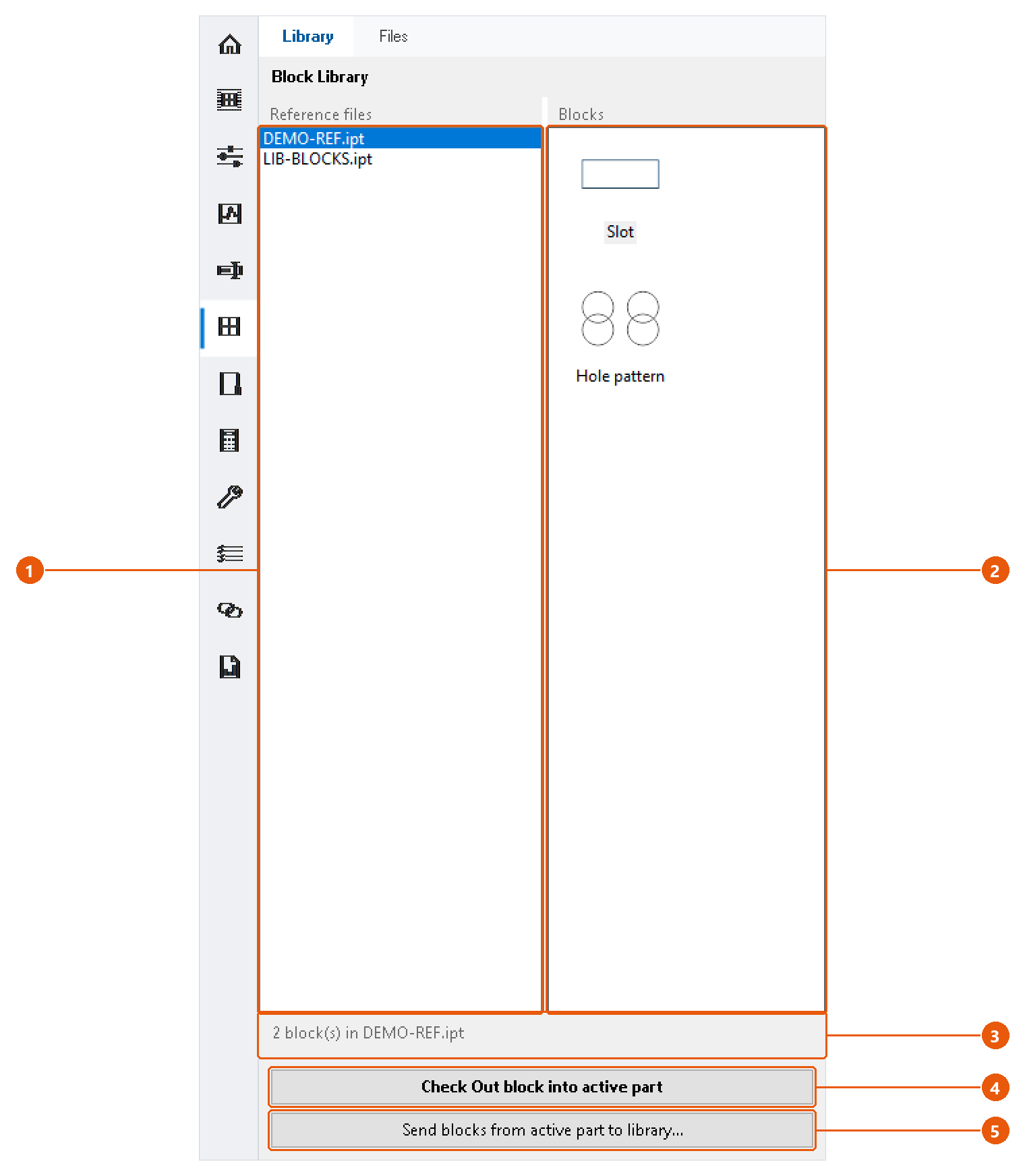
- Open the part that should receive the block. It must be the active document.
- Click Blocks in the icon bar, then the Library tab.
- Select a library file 1. Its blocks appear with a preview 2, and the status line 3 says how many there are.
- Select a block and press Check Out block into active part 4, or double-click the block.
The block is copied into the active part as an independent, editable definition. Changing it later does not change the library.
Send blocks to a library
- Open the part whose blocks you want to keep, and make it the active document.
- Press Send blocks from active part to library... 5.
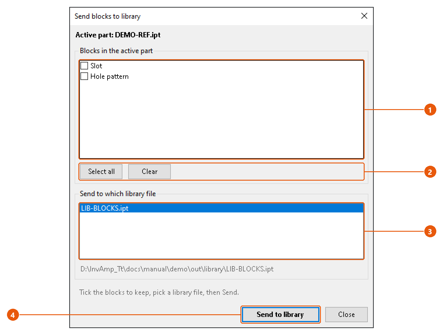
- Tick the blocks to send 1. Select all and Clear 2 tick or untick them all.
- Choose the library file to write into 3. The line below the list shows its full path. The active part itself is not offered.
- Press Send to library 4.
InvAmp writes the blocks into the library file and saves it. The result is reported for each block.
Workspace — reuse components from your folders
Workspace browses your own component folders and takes parts and assemblies into the current job: placed, derived or copied.
Register folders
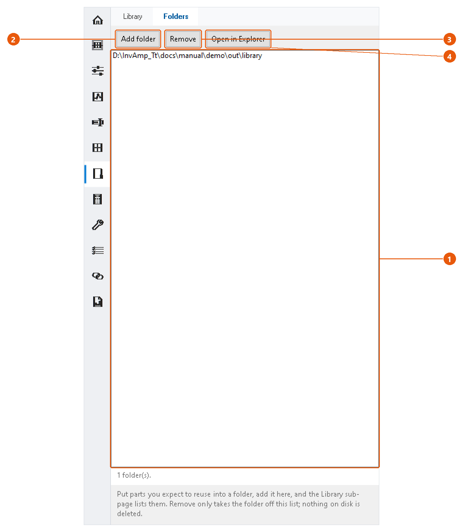
- Click Workspace in the icon bar, then the Folders tab.
- Press Add folder 2 and choose a folder that holds reusable components.
- The folders appear in the list 1. Remove 3 drops a folder from the list; it deletes nothing on disk. Open in Explorer 4 shows the folder in Windows.
Find a component
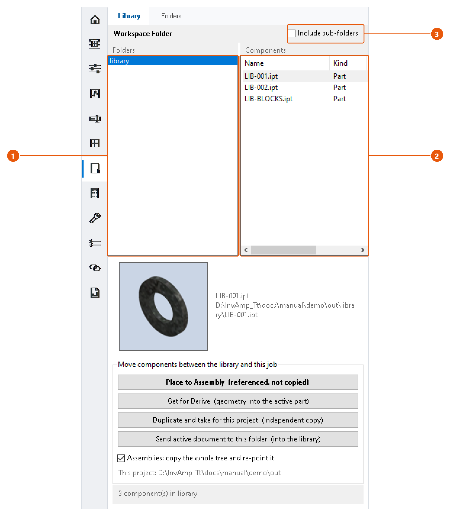
- Open the assembly or part you are working on.
- Click Workspace in the icon bar, then the Library tab.
- Select a folder 1. Its parts and assemblies appear on the right 2. Tick Include sub-folders 3 to list the sub-folders' components too.
- Select one or more components. Ctrl-click to select several.
Take it into the job
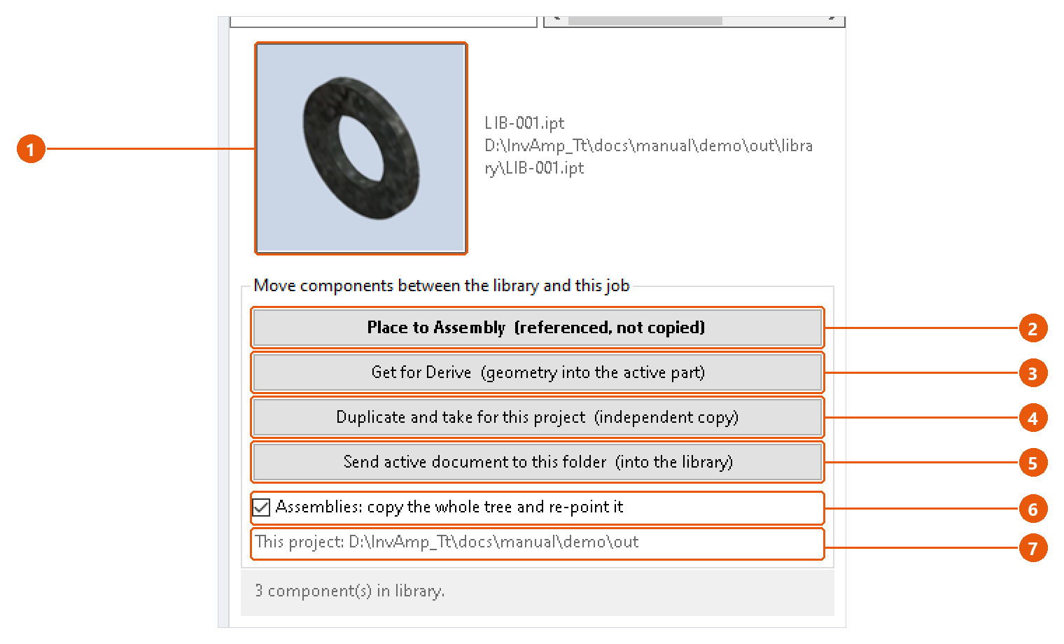
The selected component's preview and path appear at the top 1. Then choose an action:
| Action | Result |
|---|---|
| Place to Assembly 2 | Places the library file itself into the active assembly. It is referenced, not copied. Double-clicking a component does the same. |
| Get for Derive 3 | Derives the component's geometry into the active part. |
| Duplicate and take for this project 4 | Copies the component into this project's folder under a name you type, one component at a time. The copy is independent of the library. |
For assemblies, tick Assemblies: copy the whole tree and re-point it 6 to copy every part the assembly uses as well.
The project folder 7 is the folder of the active document. Save the document once if InvAmp says it cannot work it out.
Add the active document to the library
- Select the library folder on the left.
- Press Send active document to this folder 5.
The document must be a saved part or assembly with no unsaved changes, because the library copy is made from the file on disk.
Eng. Tools — calculators and tables
Eng. Tools has two tabs: cylinder force calculators, and standard part tables you can filter and extend.
Calculate a pneumatic cylinder
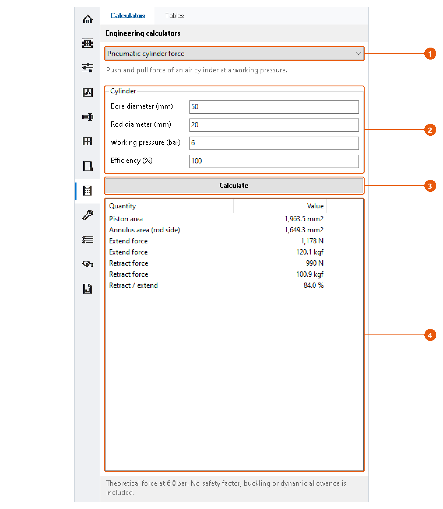
- Click Eng. Tools in the icon bar, then the Calculators tab.
- Choose Pneumatic cylinder force 1.
- Enter the bore and rod diameters, the working pressure and the efficiency 2.
- Press Calculate 3.
- Read the results 4: piston and annulus area, extend and retract force in newtons and kilograms-force, and the ratio between them.
Calculate a hydraulic cylinder
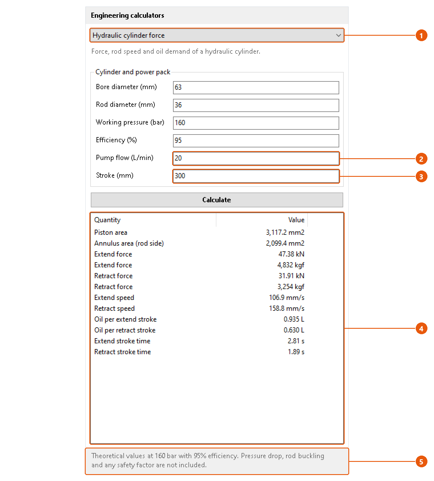
- Choose Hydraulic cylinder force 1.
- Enter the cylinder data, then the pump flow 2 and the stroke 3.
- Press Calculate.
- Read the results 4: forces in kilonewtons and kilograms-force, rod speeds, the oil used per stroke and the stroke times.
The status line 5 repeats the pressure and efficiency the figures were calculated at.
Note:The values are theoretical. Pressure drop, rod buckling, dynamic loads and safety factors are not included.
Tip: Each calculator keeps its numbers while Inventor runs, so you can switch between them without retyping.
Look up a standard part
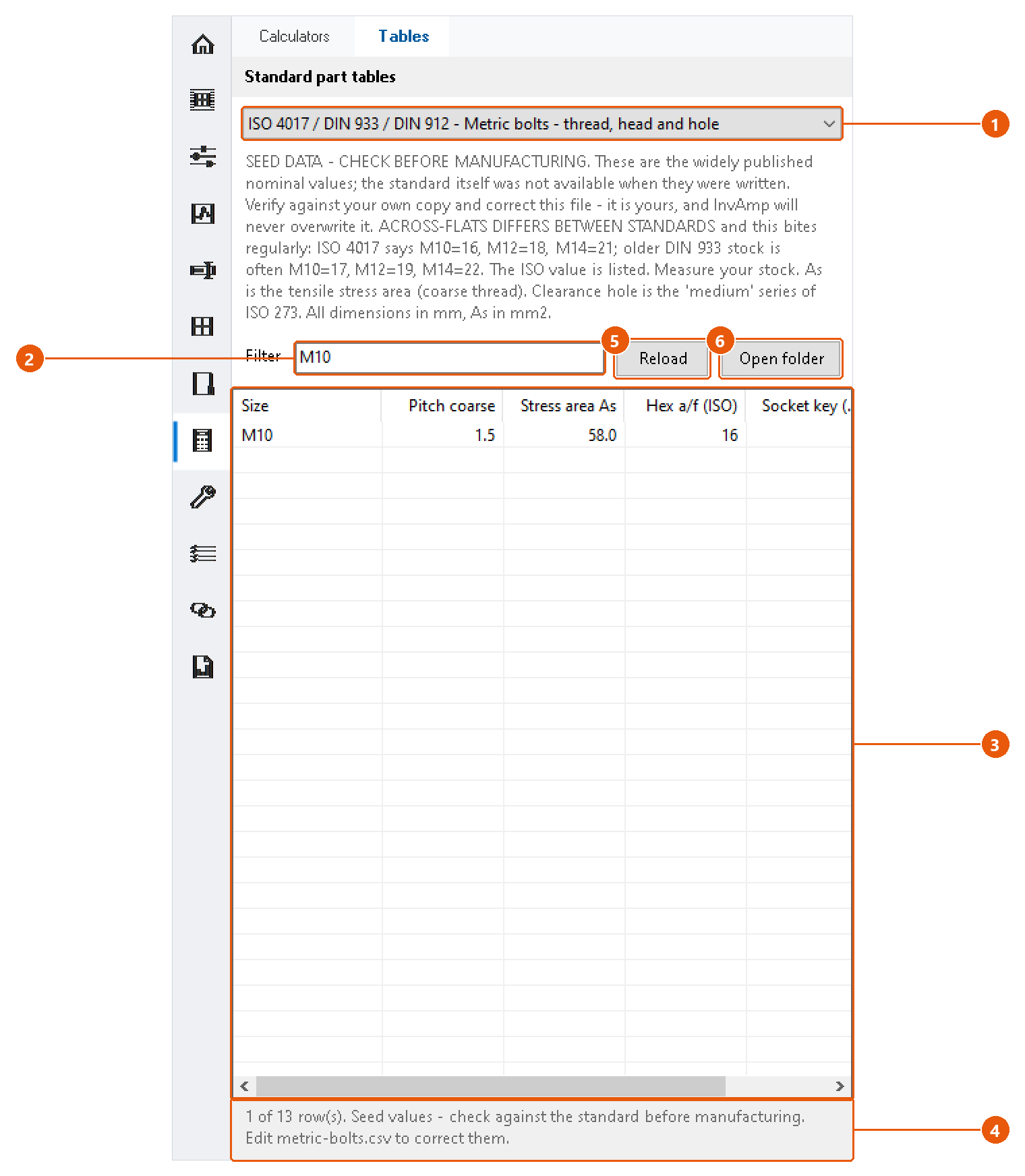
- Click the Tables tab.
- Choose a table 1. InvAmp comes with three: DIN 471 retaining rings for shafts, DIN 6885 parallel keys and keyways, and metric bolts (thread, head and hole).
- Type in Filter 2 to show only the rows that contain that text, for example
M10. - Read the rows 3. The status line 4 says how many rows match.
Note:The tables are seed data. Check them against your own copy of the standard before you manufacture to them.
Correct or add a table
The tables are CSV files in %APPDATA%\InvAmp\tables. InvAmp never overwrites them, so your corrections stay.
- Press Open folder 6.
- Edit a file, or add your own. Separate the columns with semicolons (
;), so a decimal comma never splits a value. A line#!title: ...gives the table its name, and#!standard: ...the standard it follows. - Press Reload 5.
If you delete one of the three built-in files, InvAmp writes it again the next time the page loads.
Utilities — tools for the active document
The upper part of Utilities works on the document you have open: its parameters, its drawing, a PDF, and its work planes and axes.
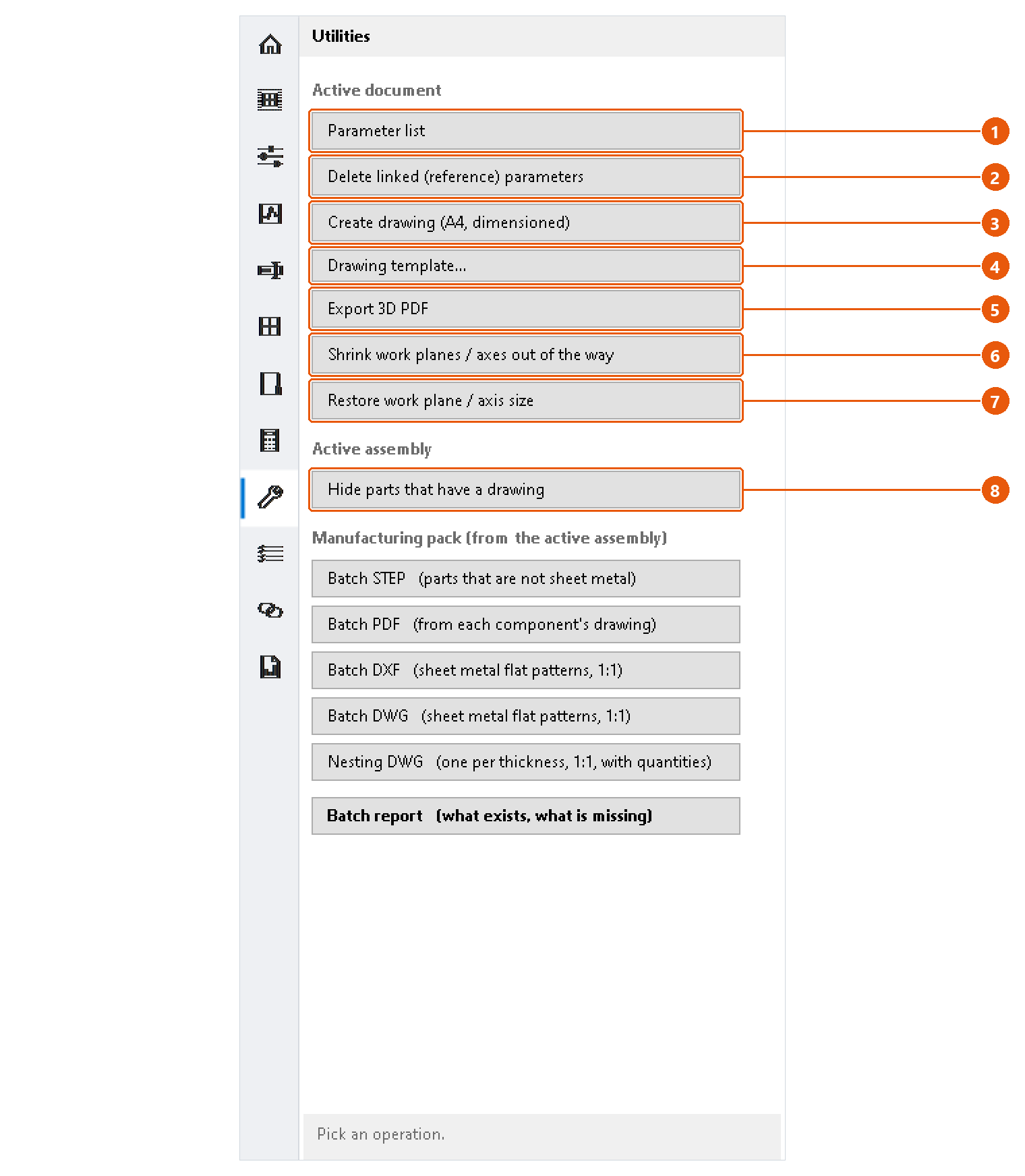
See every parameter
Press Parameter list 1. Every parameter of the active document opens in a window; see the end of this page.
Remove linked parameters
Press Delete linked (reference) parameters 2 and confirm. InvAmp deletes every reference parameter from the active document and says how many.
Note:This cannot be undone from InvAmp. Use Inventor's Undo, or close the document without saving.
Create a drawing
- Select a part in the assembly, or make the part the active document.
- Press Create drawing (A4, dimensioned) 3.
- The first time, choose your drawing template. InvAmp remembers it. Use Drawing template... 4 to change it later.
InvAmp writes the drawing beside the model as <model>.idw and saves it. What it draws depends on the kind of part, and the status line says which layout it chose. Anything it could not finish, and any drawing rule the finished sheet breaks, is listed on the status line in orange.
InvAmp decides the layout from the model:
| Model | Drawn as |
|---|---|
| A part made with sheet metal features | Sheet metal |
| A turned part, round about one axis | Shaft, with an axial section |
| Any other part | Plate |
| An assembly | Assembly |
A part saved in the sheet metal template but made without any sheet metal feature, such as a revolved ring, is drawn by its shape, not as sheet metal.
Export a 3D PDF
Press Export 3D PDF 5, choose where to save, and press Save. The default name is <document>_3D.pdf.
Note:InvAmp uses Inventor's own PDF translator. Whether the result is a true 3D PDF depends on Inventor's PDF options for the document type.
Tidy up work planes and axes
- Shrink work planes / axes out of the way 6 collapses the selected work planes and axes to nothing. They stay where they are, so they still work as references.
- Restore work plane / axis size 7 gives them back to Inventor's automatic sizing.
With nothing selected, InvAmp offers the whole document and says how many features that is. Origin planes and axes are never touched.
Hide parts that already have a drawing
- Open an assembly.
- Press Hide parts that have a drawing 8.
- Choose the folder that holds the drawings.
Parts with a drawing are hidden, so what stays on screen still needs one. A drawing counts when it has the part's file name, as .idw or .dwg, in that folder or beside the part.
The parameter list window
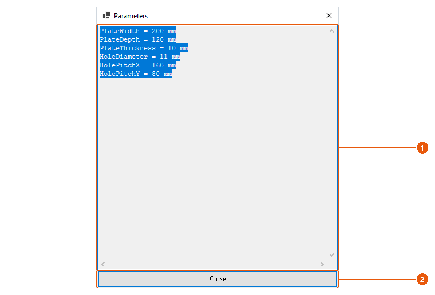
- Read the list 1. Each line is
name = expression; select and copy the text if you need it elsewhere. - Press Close 2. The status line says how many parameters there are.
Utilities — manufacturing pack
The Manufacturing pack section writes the files a shop needs to make the open assembly. Each button knows which parts it is for, and everything lands in one Manufacturing folder beside the assembly.
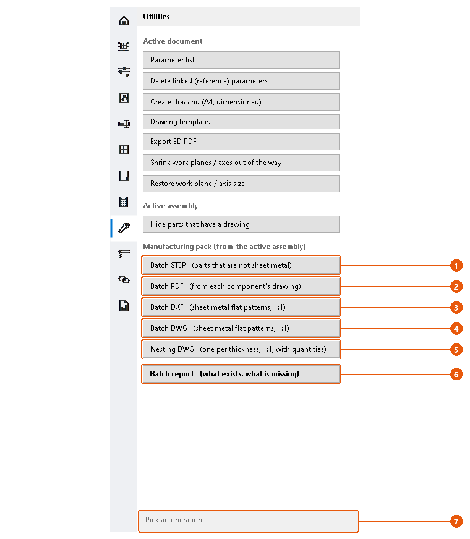
Export the pack
- Open the assembly and save it. The pack is written beside the saved file.
- Click Utilities in the icon bar.
- Press the export you need:
| Button | What it writes | Folder |
|---|---|---|
| Batch STEP 1 | One STEP file for every part that is not sheet metal. | Manufacturing\STEP |
| Batch PDF 2 | One PDF for every component that has a drawing beside it, exported from that drawing. | Manufacturing\PDF |
| Batch DXF 3 | The flat pattern of every sheet metal part, at 1:1. | Manufacturing\DXF |
| Batch DWG 4 | The same flat patterns as AutoCAD DWG. | Manufacturing\DWG |
| Nesting DWG 5 | One DWG per material thickness, every flat pattern on it at 1:1 with its part number and quantity. | Manufacturing\NESTING |
A progress window shows while the export runs; press its cancel button to stop. When an export finishes, its report opens on its own. The status line 7 repeats the summary and names the folder.
Flat patterns are written from the flat pattern's own geometry, not from a drawing view, so they cannot come out at the wrong scale.
Note:Suppressed components, and components marked Reference in the BOM, are skipped: nobody makes them.
Note: A sheet metal part with no flat pattern is unfolded for the export. If that part was open in Inventor, it stays unfolded and modified; the report says so in its Note column.
Read the report
Press Batch report 6 at any time to see what exists without exporting anything.
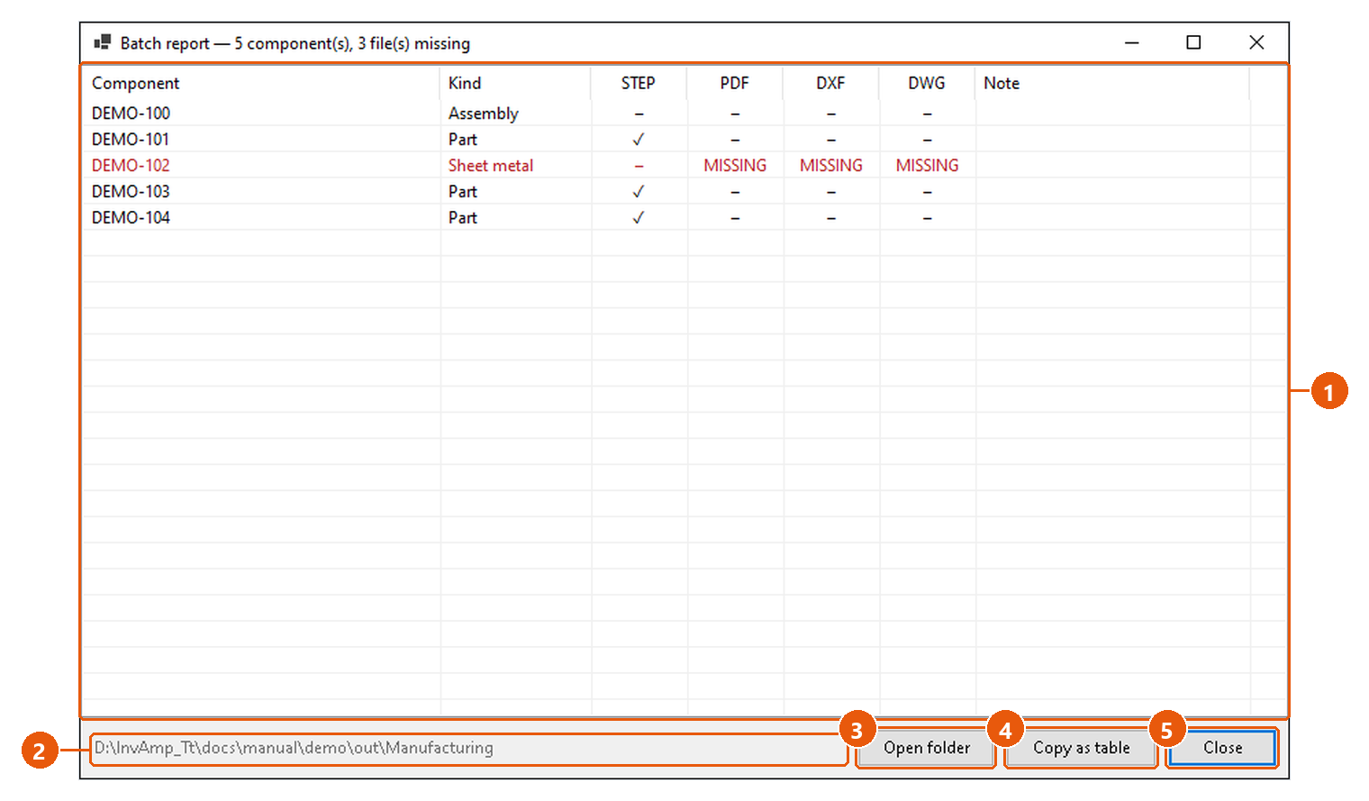
- Read the table 1. Each component has one column per format. A tick means the file exists,
–means the format does not apply, and MISSING in red means it applies but the file is not there. - The folder 2 is where the pack lives. Open folder 3 shows it in Windows Explorer.
- Copy as table 4 copies the report for a spreadsheet.
- Press Close 5.
Tip:Run Assembly Tools → Check → Sheet metal before Nesting DWG. It lists the parts whose flat pattern or thickness would come out wrong.
BOM — bill of materials
BOM lists the open assembly's components with their properties, previews and masses, and exports the list to Excel or Google Sheets.
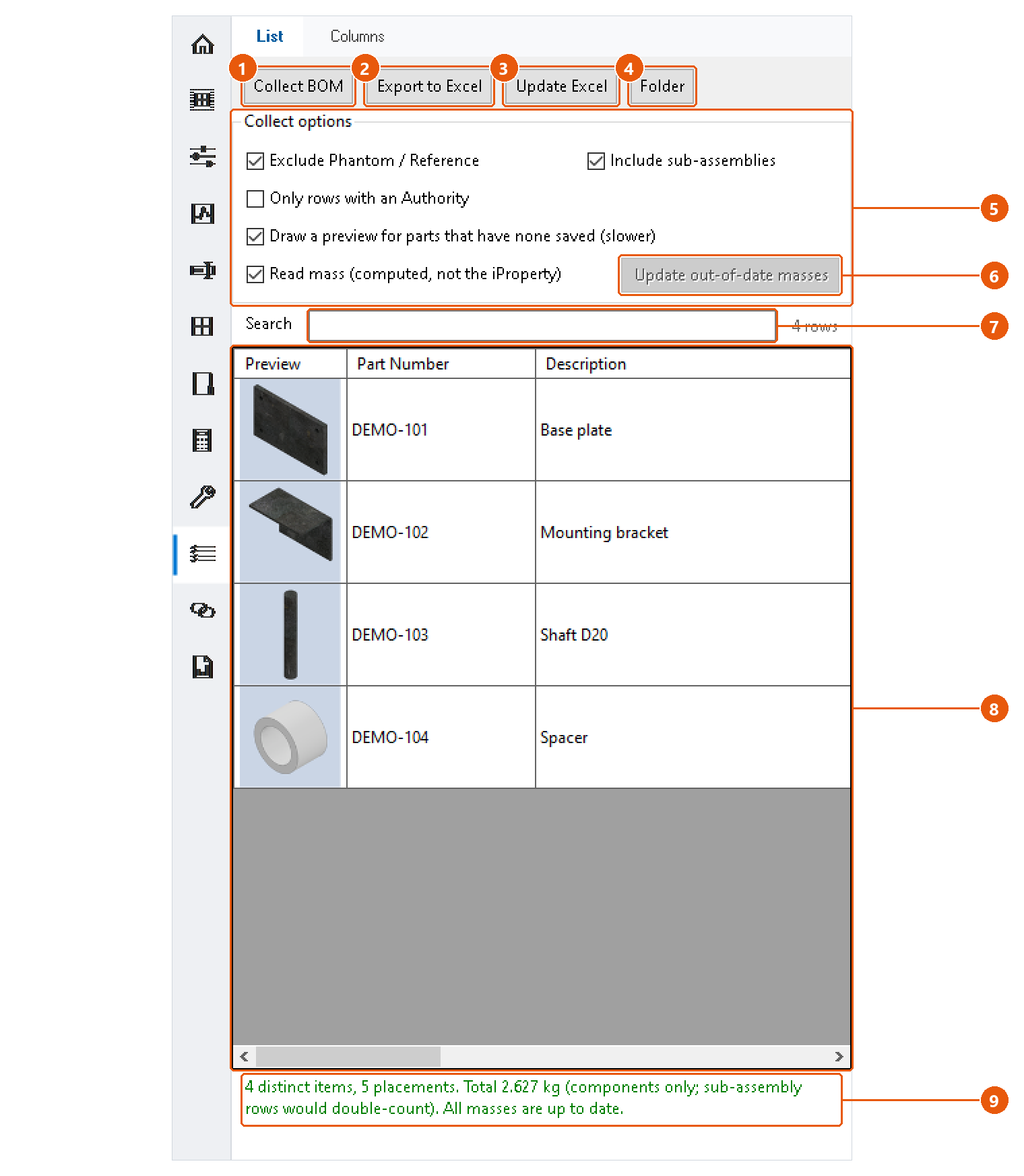
Collect the BOM
- Open the assembly and click BOM in the icon bar, then the List tab.
- Set the collect options 5:
| Option | Effect |
|---|---|
| Exclude Phantom / Reference | Leaves out components whose BOM structure is Phantom or Reference. |
| Include sub-assemblies | Lists the parts inside sub-assemblies as rows of their own. |
| Only rows with an Authority | Keeps only components whose Authority property is filled in. |
| Draw a preview for parts that have none saved | Renders a preview where the file carries none. Slower. |
| Read mass | Reads the mass computed from the geometry, not the stored iProperty. |
- Press Collect BOM 1.
Components are de-duplicated by file: a part used three times is one row with a quantity of three. The status line 9 gives the number of distinct items and placements, and the total mass.
Work with the list
- Type in Search 7 to show only the rows that contain that text.
- Double-click a row in the list 8 to select that component in Inventor.
- The columns are those of the Columns tab.
Check the masses
With Read mass on, InvAmp flags masses it does not trust: out of date, overridden in iProperties, or missing. The Mass check column names each affected row.
Press Update out-of-date masses 6 to have Inventor recompute those documents. They are not saved: save them yourself to keep the new mass on disk.
Note:With sub-assemblies included, the total counts only components, because a sub-assembly's mass already contains its parts.
Export
- Press Export to Excel 2.
- Choose where the BOM goes: Excel or Google Sheets.
- For Excel, choose the file name and folder. The workbook opens after export if Open the workbook after export is ticked on the Columns tab.
Update Excel 3 writes the same workbook again without asking. Folder 4 opens the folder of the last export.
For Google Sheets there are two cases:
- With a Google account set up in Settings, the BOM is uploaded into your Google Drive as a sheet. Update Excel updates that same sheet, so a link you already shared keeps working.
- Without one, the workbook is saved into your Google Drive folder on this computer, and Drive syncs it.
If any mass is not trustworthy, InvAmp asks before exporting.
BOM — columns
The Columns tab decides what the BOM list shows and what the export contains. Both use the same columns in the same order.
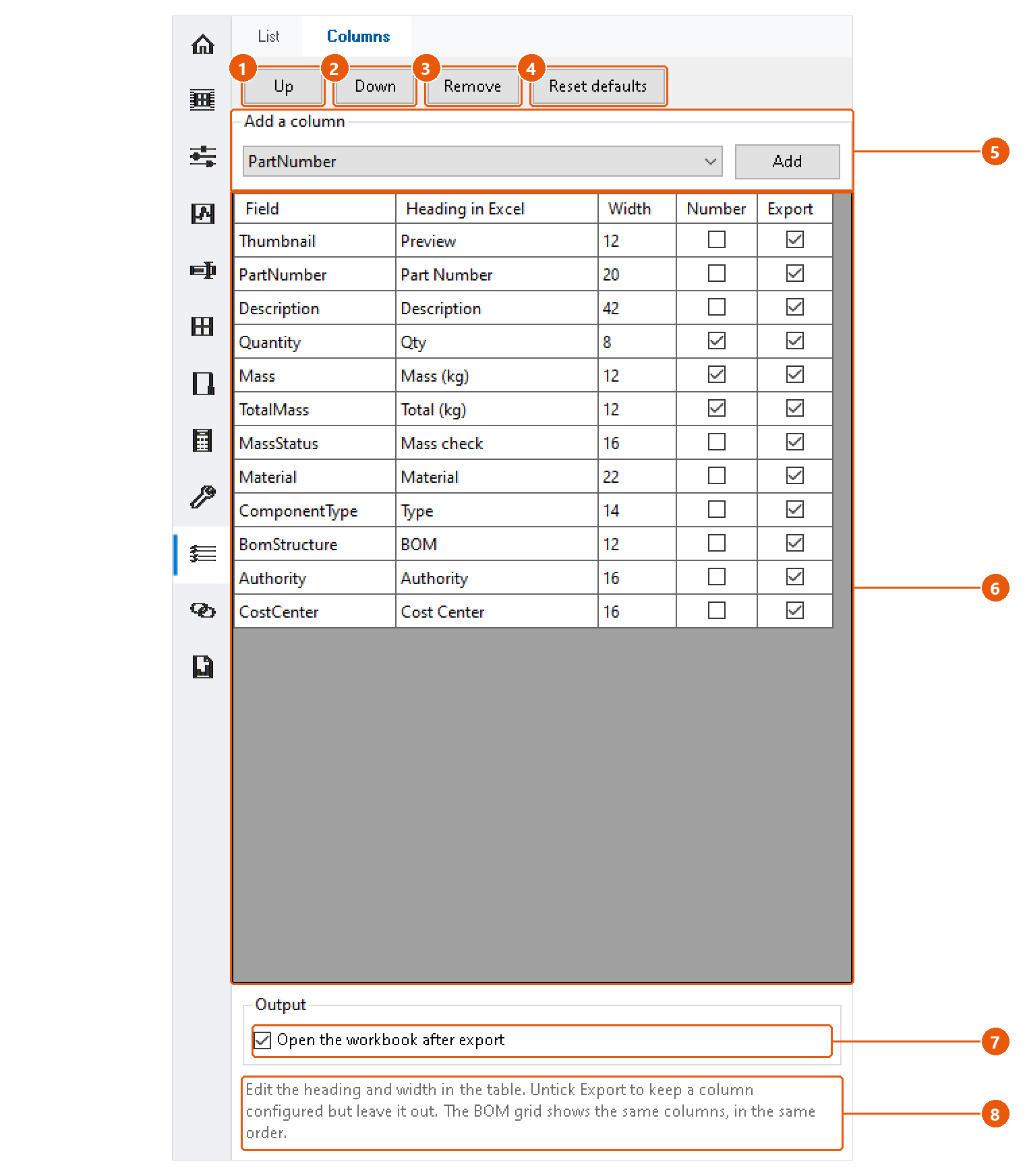
Change the columns
- Click BOM in the icon bar, then the Columns tab.
- Edit the table 6 directly:
| Column | Meaning |
|---|---|
| Field | The property the column shows. |
| Heading in Excel | The column heading in the workbook. |
| Width | The column width in the workbook. |
| Number | Writes the value as a number, so Excel can calculate with it. |
| Export | Untick to keep the column configured but leave it out. |
- To add a column, choose a field under Add a column 5 and press Add.
- Select a row and press Up 1 or Down 2 to move it, or Remove 3 to delete it.
- Reset defaults 4 brings back the built-in column set.
Changes are saved as you make them. Press Collect BOM on the List tab again to see them in the list.
Output
Tick Open the workbook after export 7 to open each exported workbook straight away.
The hint below the table 8 repeats how the table works.
Linked Params — parameters from a reference part
Linked Params copies parameters from a reference part into the document you are working on. It can also derive the reference part's geometry into the active part.
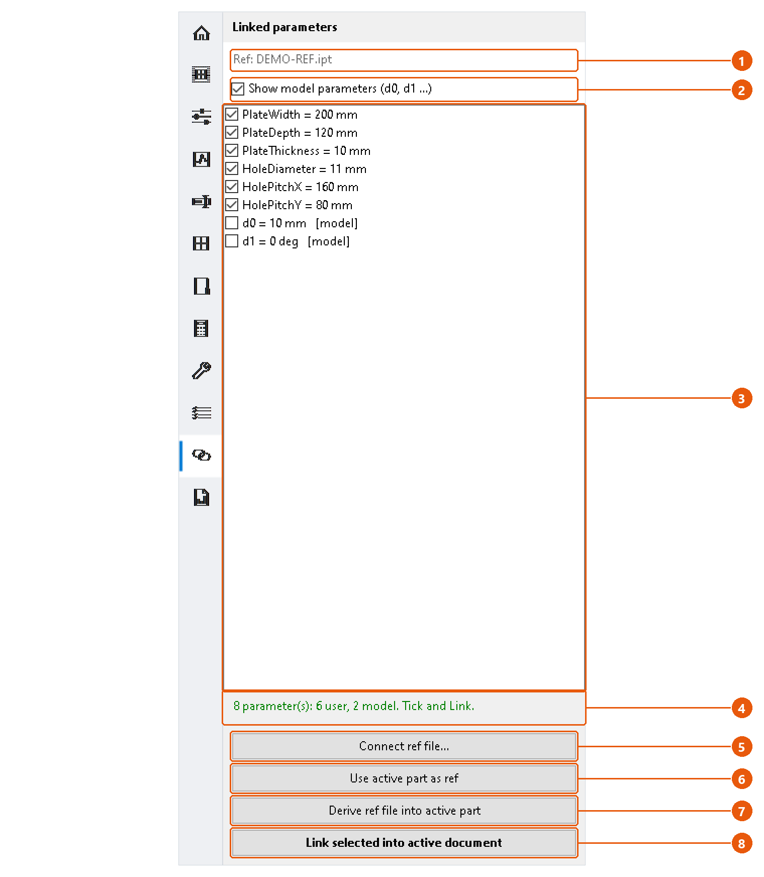
Connect a reference part
- Click Linked Params in the icon bar.
- Press Connect ref file... 5 and choose a part. Or open the reference part, make it active, and press Use active part as ref 6.
- Check the reference line 1. It names the connected file.
- Read the parameter list 3. User parameters are ticked; tick or untick them as needed.
- Tick Show model parameters 2 to list the model parameters (
d0,d1...) as well. They are never ticked for you.
The status line 4 says how many user and model parameters the reference holds.
Link parameters
- Make the document that should receive the parameters the active one.
- Press Link selected into active document 8.
The ticked parameters are created in the active document as reference parameters. Their values are copied at that moment; they do not follow later changes in the reference part. Parameters that already exist in the active document are skipped, and the status line says so.
Note:If the reference part is the active document, Link stops and asks you to switch to the document the parameters should go into.
Derive the geometry
Press Derive ref file into active part 7. The reference part's solid is brought into the active part as a derived component. Unlike linked parameters, it updates when the reference part changes.
Tip:An assembly can be connected for Derive, but its parameters cannot be listed. The status line says so.
To remove linked parameters again, use Utilities → Delete linked (reference) parameters.
Design Report
Design Report runs a set of design checks over the open assembly, lets you work through the issues, and writes them to a PDF with an ISO 7200 title block.
Run the report
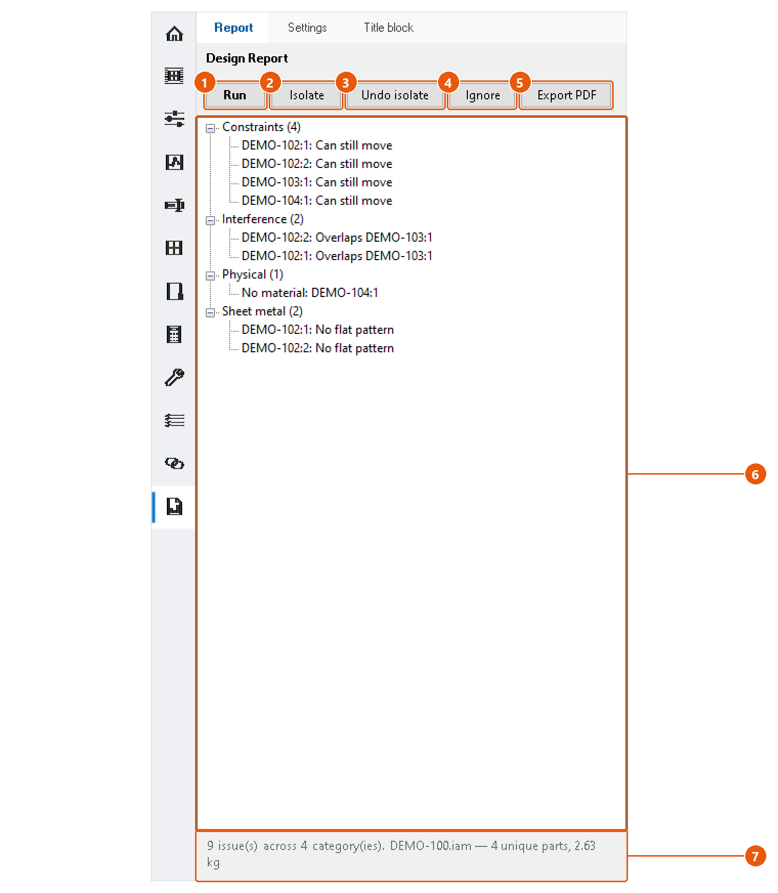
- Open the assembly and click Design Report in the icon bar, then the Report tab.
- Press Run 1.
- Read the issues 6. They are grouped by category, with the number of issues in brackets.
- The status line 7 gives the issue and category count, the assembly name, the number of unique parts and the total mass.
Work through the issues
- Double-click an issue to zoom to its components.
- Select an issue and press Isolate 2 to show only its components. Undo isolate 3 brings the rest back.
- Select an issue and press Ignore 4 to remove it. It stays out of later runs and the PDF while Inventor is open.
Export the PDF
Press Export PDF 5. The first time, choose the folder the reports go to.
The PDF is named <assembly>_DesignReport_<date>_<time>.pdf and opens when it is written. It has an isometric view of the assembly on the cover, your logo, and the title block on every page.
Report settings
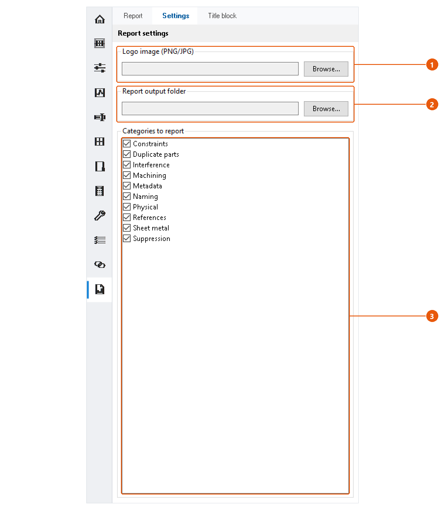
- Click the Settings tab.
- Choose a logo image for the report 1, PNG or JPG.
- Choose the folder the reports are written to 2.
- Untick the categories you do not want to check 3. There are ten: Constraints, Duplicate parts, Interference, Machining, Metadata, Naming, Physical, References, Sheet metal and Suppression.
Title block
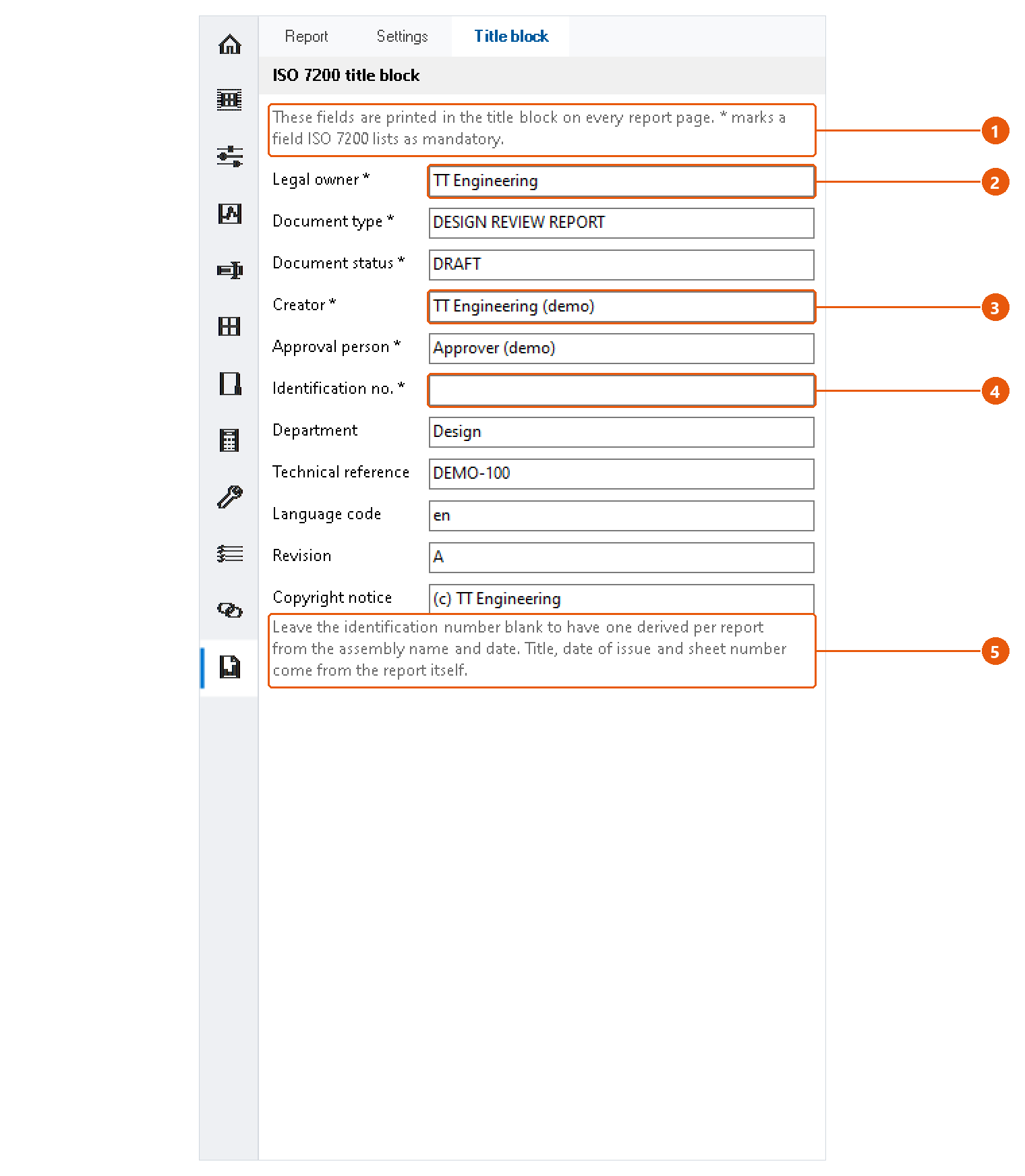
The title block fields 1 are printed on every page of every report, so they are entered once.
- Click the Title block tab.
- Fill in the fields, for example the legal owner 2 and the creator 3. A star marks the fields ISO 7200 lists as mandatory.
- Leave the identification number 4 blank to have one made for each report from the assembly name and the date.
Title, date of issue and sheet number come from the report itself 5.
Note:The creator starts as your Windows user name. Change it if the report should name someone else.
Settings
Every InvAmp preference is on Home → Settings. Changes are saved straight away; there is no Save button. The page scrolls: the last groups are below the fold.
AutoSave reminder

Tick Remind me to save the open document 1 and set the interval in minutes 2. When the time comes and the active document has unsaved changes, InvAmp asks whether to save it. It never saves without asking.
Appearance
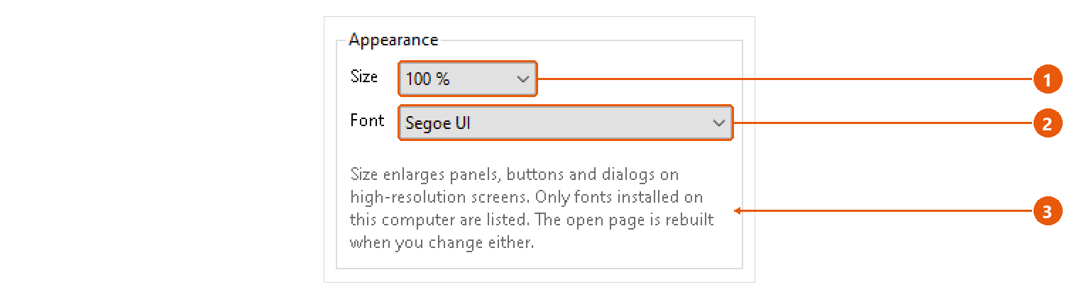
- Size 1 enlarges panels, buttons and dialogs, for high-resolution screens.
- Font 2 sets the typeface. Only fonts installed on this computer are listed.
The open page is rebuilt when you change either 3. Anything typed on it but not yet applied is lost.
Panels
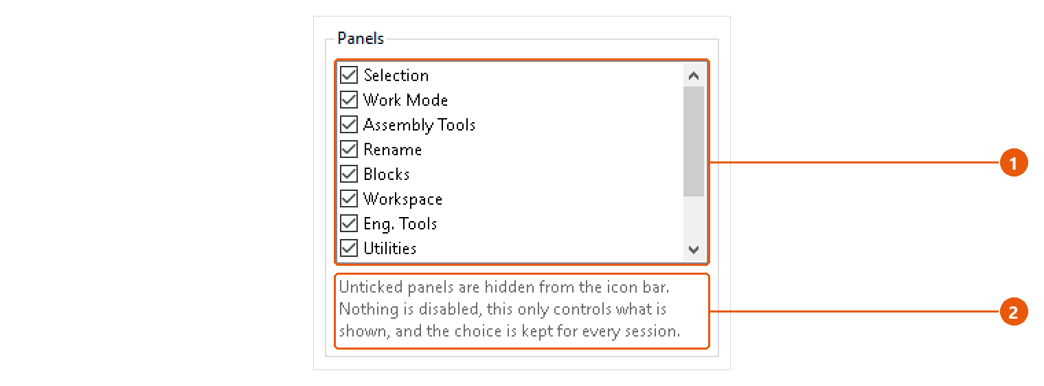
Untick a page 1 to hide it from the icon bar. Nothing is disabled: the choice only controls what is shown 2, and it is kept for every session. Home cannot be hidden.
Assembly tools
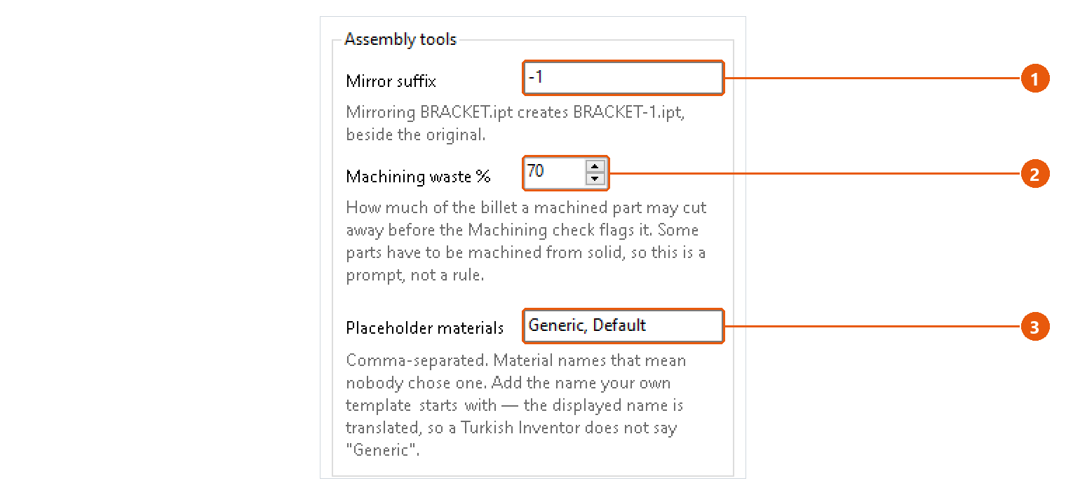
| Setting | Used by |
|---|---|
| Mirror suffix 1 | Assembly Tools → Mirror part. Added to the source name: BRACKET.ipt becomes BRACKET-1.ipt. |
| Machining waste % 2 | Assembly Tools → Check → Machining. Above this share of the billet cut away, a part is flagged. 70 % by default. |
| Placeholder materials 3 | Assembly Tools → Check → No material. Comma-separated material names that mean nobody chose one. Generic, Default by default. |
Drawing
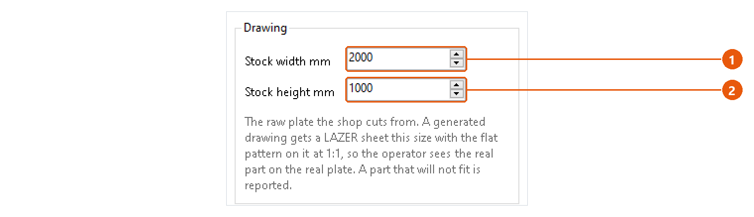
Stock width mm 1 and Stock height mm 2 are the raw plate the shop cuts from. A generated sheet metal drawing gets a sheet this size with the flat pattern on it at 1:1, so the operator sees the real part on the real plate. A part that does not fit is reported.
Google account
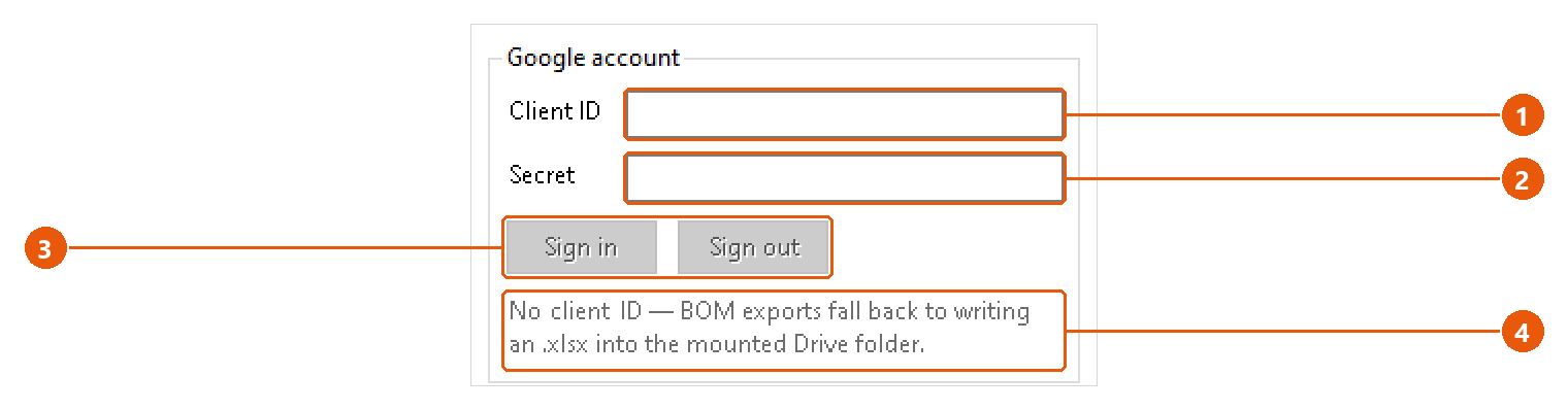
Needed only to export a BOM straight into Google Sheets.
- Enter your own Google OAuth Client ID 1 and Secret 2.
- Press Sign in 3 and complete the sign-in in your browser. Sign out forgets the account.
The status line 4 says whether the account is set up and signed in. Without a client ID, a BOM headed for Google Sheets is saved as an .xlsx into your Google Drive folder instead.
Support
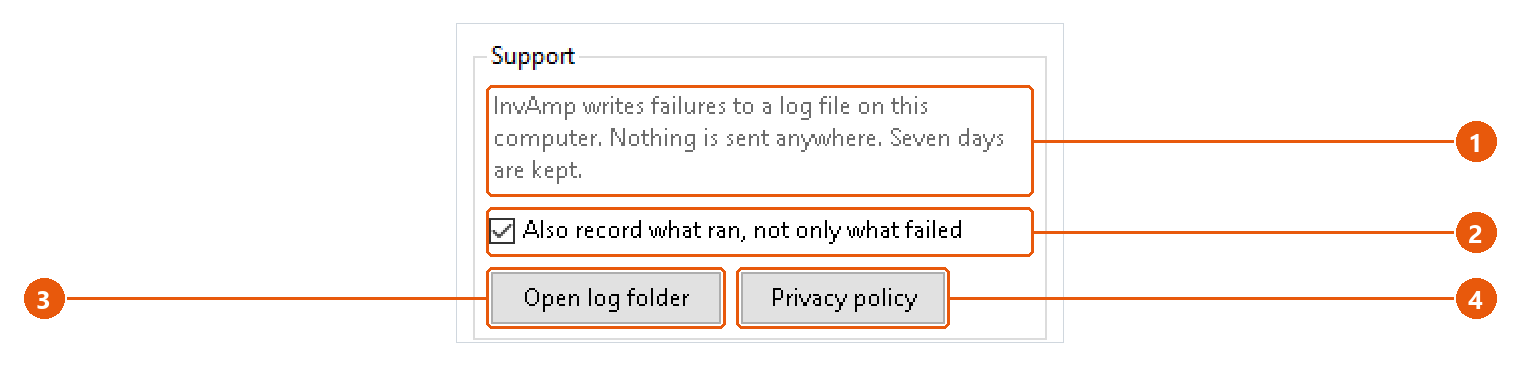
InvAmp writes failures to a log file on this computer 1. Nothing is sent anywhere, and seven days are kept.
- Tick Also record what ran, not only what failed 2 when support asks for a fuller log. It takes effect at once.
- Open log folder 3 shows the log in Windows Explorer.
- Privacy policy 4 shows the policy that ships with InvAmp. It opens without an internet connection.
Troubleshooting — messages and the log
Read the status line first
Most pages say what went wrong on their status line, in red, in words you can act on.
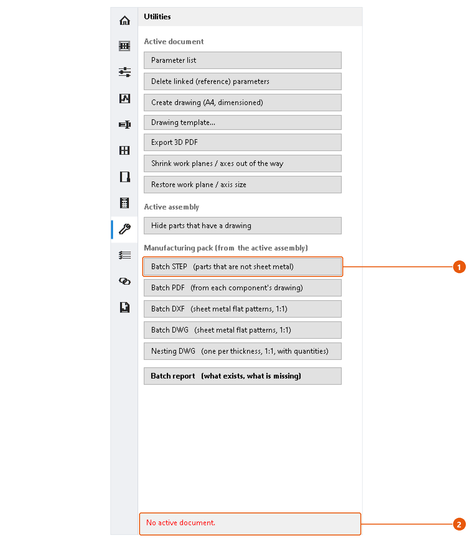
Here Batch STEP 1 was pressed with no document open, and the status line 2 says so. The messages you will meet most often:
| Message | What to do |
|---|---|
| No active document. | Open the part or assembly first. |
| Open an assembly first. | The tool works inside an assembly. Open one and make it the active document. |
| Select a component in the assembly. | Select the component in the browser or the graphics window, then press the button again. |
| Save the assembly first — the pack is written beside it. | Save the assembly once; the manufacturing pack goes into a folder next to it. |
| This component is grounded. Unground it first, or it cannot be constrained. | Unground the component in the browser. |
Settings are not remembered
InvAmp writes to %APPDATA%\InvAmp\settings.ini. When the file cannot be written, InvAmp says so in a message that names the file. Your changes then last only until Inventor closes. A file sync client or an antivirus holding the file open is the usual cause.
Nesting skipped a part
The part probably has no flat pattern. Run Assembly Tools → Check → Sheet metal; it lists exactly those parts.
Send us the log
- Open Home → Settings → Support and press Open log folder.
- E-mail the newest file from that folder to info@invamp.net, with the add-in version from Home → Environment.
If a problem leaves nothing in the log, tick Also record what ran, not only what failed, repeat what you did, and send the log again.
Tip:New versions, videos and this help are on invamp.net.
Troubleshooting — the panel
The InvAmp button is not on the Tools tab
- Restart Inventor. Add-ins are loaded only at start-up.
- Open Tools → Add-Ins. Make sure InvAmp is loaded and Load Automatically is ticked.
The panel is missing but the add-in is loaded
Press InvAmp on the Tools tab; it shows and hides the panel. If the panel was dragged off-screen, use Inventor's View → User Interface to reset the window layout.
A page is missing from the icon bar
It is probably hidden. Open Home → Settings and look at the Panels group.
- Tick the missing page in the list 1. It appears in the icon bar at once.
- Nothing was disabled while it was hidden 2: the page and its settings are just as you left them.
A page says "This page could not be loaded."
The page failed while it was being built. The message names the page and the reason. The rest of the panel keeps working. Restart Inventor; if it happens again, send the log (see below).
Inventor seems frozen during a long run
Batch exports, nesting and the assembly checks do their work inside Inventor. A progress window keeps Inventor painted and offers a cancel button. On a large assembly, Windows may still call Inventor "not responding"; wait for the run to finish.
Tip:Hover over a page's icon to check which page it is before you hide or look for it.